Here are the guidelines for users to implement Secure DFU OTA(over-the-air) while usingnRF52832 Solution modules.(Click on link for Raytac nRF52832 module series)
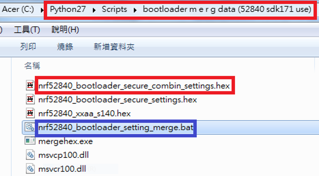
Step 1. Execute the combine batch file in bootloader (nrf52840_bootloader_setting_merge.bat) and generate file ofnrf52840_bootloader_secure_combin_settings.hex :
@echo off title = [ J-Link Tool ] %CD% set nrfDir=C:\Program Files (x86)\Nordic Semiconductor\nrf5x\bin set BS= nrf52840_bootloader_secure_settings.hex set BL= nrf52840_xxaa_s140.hex set BSBLCombind= nrf52840_bootloader_secure_combin_settings.hex set path=%nrfDir%;%path% pause echo -----------merge image file------------------- mergehex.exe -m %BS% %BL% -o %BSBLCombind% pause
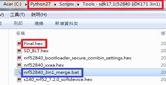
Step 2. Create a Final.hex file by 3-in-1 batch file(nrf52840_3in1_merge.bat) ※Note : This hex file is created for the production line to pre-load firmware into modules prior to shipment.
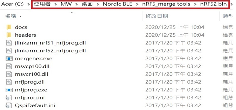
@echo off title = [ J-Link Tool ] %CD% set nrfDir=C:\Users\user\Desktop\Nordic BLE\nRF5_merge tools\nRF52 bin set SD= s140_nrf52_7.2.0_softdevice.hex set BLT= nrf52840_bootloader_secure_combin_settings.hex set APP= nrf52840_xxaa.hex set SD_BLT=SD_BLT.hex set Finalfile=Final.hex set path=%nrfDir%;%path% pause echo -----------merge image file------------------- mergehex.exe -m %SD% %BLT% -o %SD_BLT% pause mergehex.exe -m %SD_BLT% %APP% -o %Finalfile% pause
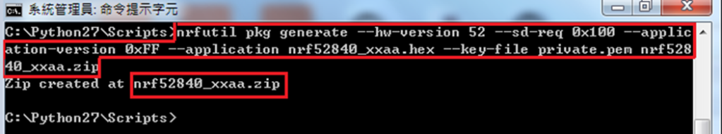
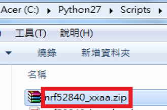
Step 3. Create a DFU(OTA).zip file of nrf52840_xxaa.zip ※Note : This zip file is created for end device DFU(OTA) implementation.
The DFU OTA zip file: nrf52840_xxaa.zip will be derived.
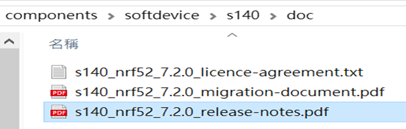
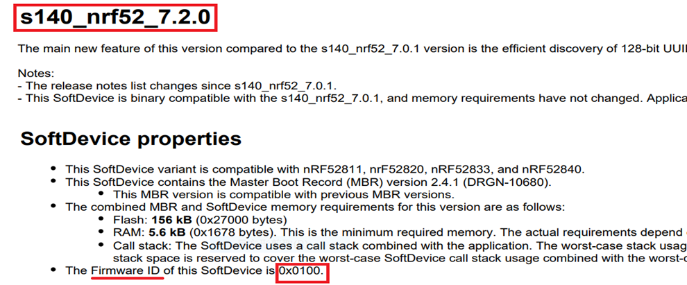
※Note : The "0x100" appeared in the above DOS code(in red font) is the FWID(Firmware ID) for s140_nrf52_7.2.0_softdevice.hex; FWID can be found from the soft device documents on the Nordic website.
Step 4: Run DFU OTA (On mobile in this example)
4A. Install the nRF Connect APP on mobile, with DFU OTA file: nrf52840_xxaa.zip.
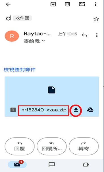
4B. Send nrf52840_xxaa.zip via email to mobile device after combination is done on PC, then download it.
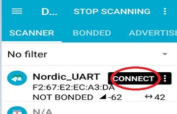
4C. Open nRF Connect APP and run connection;
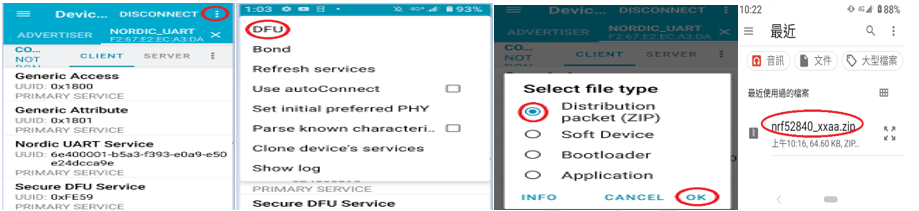
4D. Execute DFU and select "Distribution packet(ZIP)", thus starting the DFU OTA process.
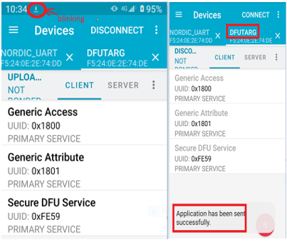
4E. Start DFU OTA → exit the APP after DFU OTA is completed → restart the mobile device.
Secure DFU OTA for nRF52840 solution modules: Guide to create hex/zip file for implementation Detailed links of articles: Part A: Bootloader(Click for article link) Part B: Application(Click for article link) Part C: Combining and merging built files (Click for article link)
Technical guidelines provided by R&D Manager: Mr. MW Lee Edited by Sales Manager: Mr. Tony Yin
Raytac Corporation 勁達國際電子股份有限公司 Bluetooth & WiFi module maker based on Nordic nRF54, nRF53, nRF52, nRF7002 solution BT5.4 &BT5.3 & BT5.2 & BT5.1 Qualified, FCC/IC/CE/Telec/KC/RCM/SRRC/NCC Pre-Certified. Bluetooth Solution: nRF54, nRF5340, nRF52840, nRF52833, nRF52832, nRF52820, nRF52811, nRF52810, nRF52805, nRF51822 WiFi Solution: nRF7002
Before building Application code , some amendments need to be made regarding DFU-related settings and code inside Application:
Step 1.
1A. Add code in definition in C/C++ : BL_SETTINGS_ACCESS_ONLY NRF_DFU_SVCI_ENABLED NRF_DFU_TRANSPORT_BLE=1 (Total 3 steps definitions need to be set up)
1B. Add “include path” in C/C++
1C. Add the .c files inside red frame in(Screenshots 1 & 2) and the 2 groups of (nRF_DFU & nRF_SVC)(Screenshot 3) under Project(Screenshot 4)
1D. Add code into main.c file in Application (..\examples\ble_peripheral\ble_app_uart\main.c) (Please refer to: main.c file at: ..\examples\ble_peripheral\ ble_app_buttonless_dfu)
1E. The code of file: sdk_config.h (..\examples\ble_peripheral\ble_app_uart\pca10056\s140\config\ sdk_config.h) inside Application needs to be modified.
1F. Adjust the IRAM1 value in Target after implementing DFU service: Check on the IRAM1 Value of *p_app_ram_start to be modified from default: 0x20002AE8 0x3D518 to 0x20002AF8 0x3D508, as shown in the red frame in the bottom right corner. In this case, the program should run successfully.
1G: Create a file of:nrf52840_xxaa.hexafter building application code files.
Step 2. Create a bootloader setting file of nrf52840_bootloader_secure_settings.hex :(via DOS)
In Nordic Semiconductor products, the enhanced APprotect feature has been integrated into the nRF52 series microcontrollers. APprotect (Access Port Protection) is a crucial security feature designed to safeguard the device's application, compiled code, with read-back protection mechanism, against unauthorized access and modifications. This protection is essential for preventing unauthorized access and software tampering.
Effectively leveraging the improved Approtect feature on nRF52 series microcontrollers to enhance device application security and reliability is a significant concern for current developers and engineers.
This year, Raytac Corporation has launched low-energy Bluetooth modules for the third edition IC nRF52840 APprotection Solution and nRF52832 APprotection Solution.
These modules not only retain the functionalities of the original nRF52840 and nRF52832 low-energy Bluetooth modules but also comprehensively upgrade security by adding the APprotect feature to prevent hackers from accessing and rewriting programs without authorization.
Here is a detailed explanation of the nRF52 third edition low-energy Bluetooth modules by Raytac Corporation:
Raytac Corporation APProtection Bluetooth Module Series:
The encoding principle is to use 'EN' after the original model number to represent 'encrypted' instead of 'V2'.
For example, in the nRF52840 series, the Raytac model MDBT50Q-1MV2 has "V2" replaced with "EN" for the third edition, hence the third edition model is named MDBT50Q-1MEN.
MDBT50Q Ceramic Antenna Series:
MDBT50Q-1MEN: Equipped with a ceramic antenna module suitable for long-distance or complex environment wireless transmission.
MDBT50Q-P PCB Antenna Series:
MDBT50Q-P1MEN: Equipped with a PCB antenna module suitable for general environment wireless transmission.
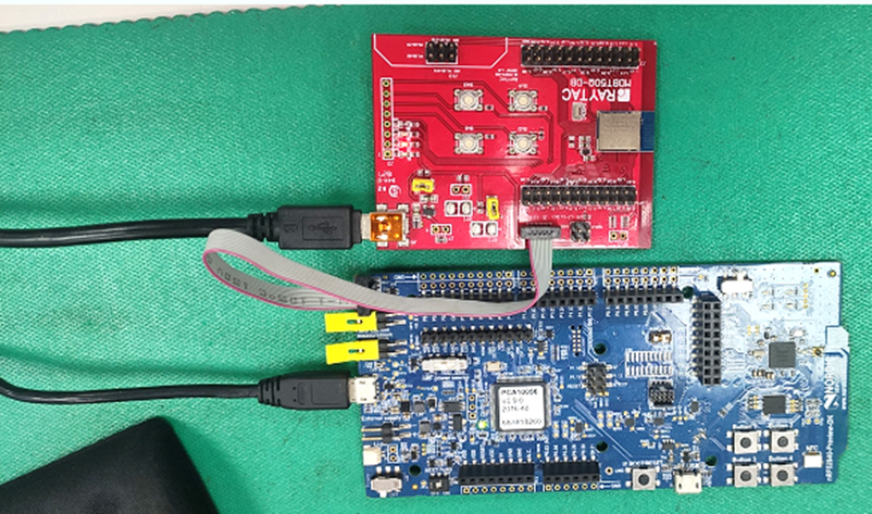
MDBT50Q-DB : An excellent choice for those who want to delve deeper into and conduct more tests with the Nordic nRF52840. This development and debugging board based on the MDBT50Q-1MV2 (ceramic antenna) module has all GPIOs of the module pulled out, facilitating rapid connection to other devices for firmware development and verification using jumper wires.
The same encoding principle applies to the nRF52832 series, and the MDBT42Q series follows suit.
MDBT42Q Ceramic Antenna Series:
MDBT42Q-512KEN comes with a ceramic antenna module, suitable for long-distance or complex environment wireless transmissions.
MDBT42Q-P PCB Antenna Series:
MDBT42Q-P512KEN features a PCB antenna module, suitable for general environment wireless transmissions.
MDBT42Q-U512KEN , designed for external antenna requirements, comes with a u.FL connector module suitable for ultra-long-distance wireless transmissions.
MDBT42Q-DB development board is based on the MDBT42Q-512KV2 (ceramic antenna) module and is designed for development and debugging purposes.
Other Reference Links:
Nordic 3rd Party Modules/Modems(Raytac's modules are all qualified Nordic 3rd Party Bluetooth low energy module, please go following website for more detailed information.)
Module Appearance: The third edition features an additional black dot in the bottom left corner of the metal shell for easy identification of its purpose.
While the device with readback protection enabled, issuing ERASEALL command is a must and the only method to unlock the device before proceeding with programming.
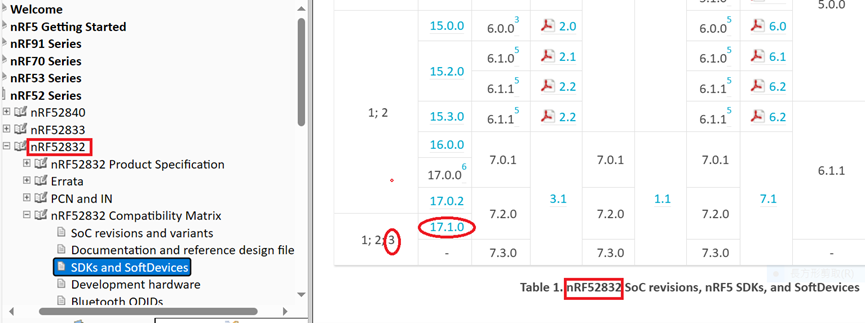
It is recommended to use nRF_SDK v17.1.0 or later versions to write code for the third edition
For further clarity on the differences between the second edition IC Bluetooth modules and the third edition IC Bluetooth modules, the following table and links are provided for reference
Raytac Corporation, a globally recognized third-party Bluetooth module supplier endorsed by Nordic Semiconductor, has announced a strategic collaboration with Millennium Semiconductor, a specialized electronic agent, starting from November 2023. The establishment of this partnership aims to jointly expand into the Indian market and provide comprehensive services to customers in different regions. Raytac Corporation has consistently focused on the wireless field, earning a reputation as a leading provider of Bluetooth Low Energy modules with outstanding technological capabilities. Additionally, Raytac offers the latest WiFi + BLE modules and a complete range of solutions from Nordic.
The product lineup includes series such as nRF54, nRF5340, nRF52840, nRF52833, nRF52832, nRF52820, nRF52811, nRF52810, nRF52805, nRF51822, all of which have obtained qualifications for BT5.4, BT5.3, BT5.2, and BT5.1. Furthermore, the nRF7002 represents the first device in our array of distinct Wi-Fi products, seamlessly combining with Nordic's established ultra-low power technologies. Raytac Corporation's modules have received Bluetooth (QDID/DID/BQB) and regulatory certifications from various countries and regions, including FCC (USA), CE (Europe), IC (Canada),TELEC (Japan), KC (Korea), SRRC (China), NCC (Taiwan), RCM (Australia/New Zealand), and others.
In addition to delivering excellent performance and transmission distances, Raytac Corporation's modules are relatively compact in size, offering a diverse range of module series choices. This flexibility empowers developers to design without being constrained by module dimensions. Furthermore, the inclusion of AT Command by Raytac facilitates a quick entry for developers into the realms of Bluetooth and the Internet of Things.
Millennium Semiconductors India Private Limited,
17/18/19, 2nd Floor, Mahalaxmi Heights, Mumbai-Pune Road, Pimpri, Pune 411 018, Maharashtra, INDIA.
When launching new products, there is a requirement for RF testing, and two methods are commonly used:
DTM (Direct Test Mode) and Radio Test.
Nordic's SDK provides two RF testing programs: DTM (Direct Test Mode) and Radio Test. While both methods can test RF indicators, they have some distinctions. DTM follows the Bluetooth specification's Direct Test Mode data format (referenced in Bluetooth Core Specification Version 5.2, Vol. 6, Part F.), primarily for Bluetooth certification tests.
On the other hand, Radio Test focuses on the chip's radio indicators, making it more suitable for FCC and ETSI certifications.
Let's delve into detailed explanations for DTM and Radio Test programs.
DTM(Direct Test Mode)
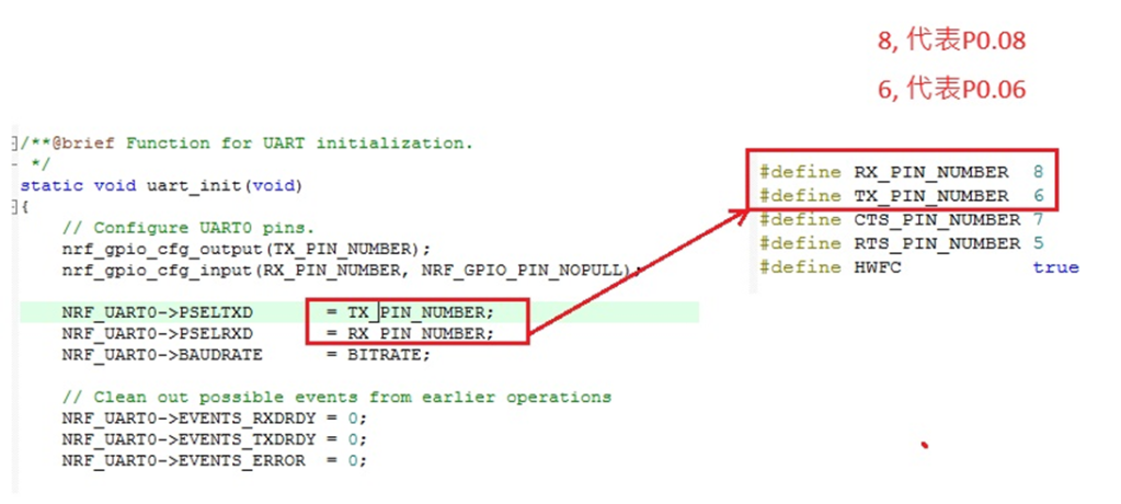
The Bluetooth Association offers a feature for testing RF characteristics. Nordic has incorporated DTM firmware into the SDK according to SIG standard documents. Customers only need to modify the Baud Rate and UART TX/RX pins to conduct RF tests.
1. Download and install nRF Connect for desktop software and nRF5 SDK from the Nordic website.
2. Install the Direct Test Mode program in the nRF Connect for desktop software.
3. Extract the SDK package, open the DTM example code from
nRF5_SDK_vxx\examples\dtm\direct_test_mode\ board number\blank, modify TX and RX pins based on the target board's definitions, then compile.
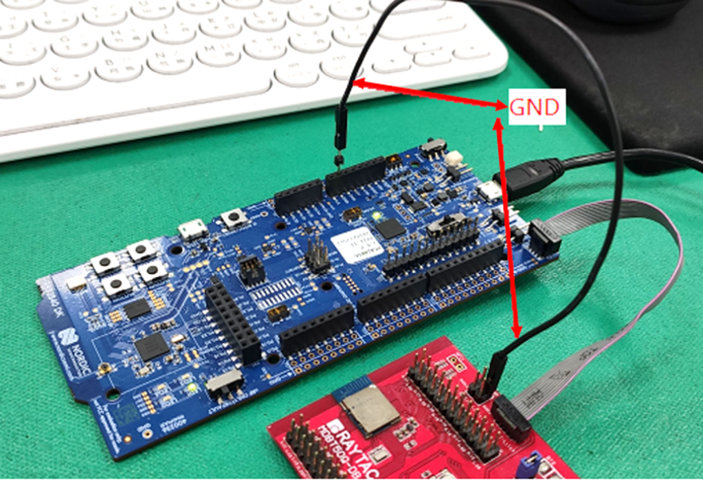
Download the program to the target board connected to the PC. (Select the appropriate sample code based on the IC/module for testing, referring to the board numberbelow. )
IC P/N
board number
NRF52832
pca10040
NRF52810
pca10040e
NRF52840
pca10056
NRF52811
pca10056e
NRF52833
pca10100
NRF52820
pca10100e
RF testing is performed using UART TX/RX commands. The SDK program defaults to certain positions, but users can modify these two pin positions according to their product design without changing the Baud Rate setting.
UART Pin
nRF51
nRF52
TXD
P0.09
P0.06
RXD
P0.11
P0.08
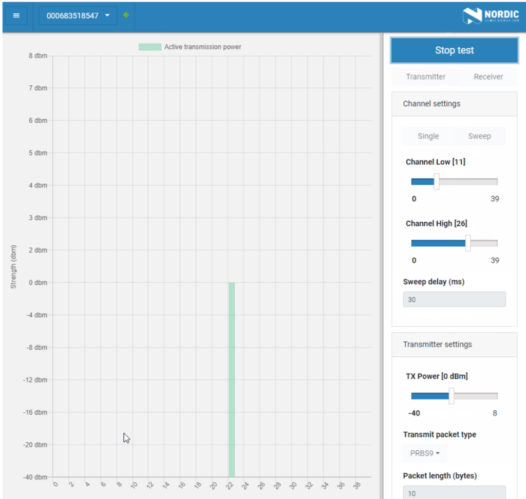
4. Use nRFConnect DTM for testing by adjusting UART TX/RX pins.
Nordic provides a tool for simpler RF testing, allowing the configuration of radio-related data such as TX power, frequency, TX carrier, and TX modulation carrier through a Command List. It doesn't include testing for RX sensitivity; if needed, users must either write a program for this test or use DTM for testing.
1. Open from nRF5_SDK_vxx\examples\peripheral\radio_test\board number\blank (Based on the IC/module for testing, referring to the board number below.)
IC P/N
board number
NRF52832
pca10040
NRF52810
pca10040e
NRF52840
pca10056
NRF52811
pca10056e
NRF52833
pca10100
NRF52820
pca10100e
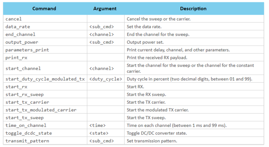
2. This test also utilizes a Command-based approach to send instructions for different parameter tests. Compared to DTM, Radio Test is more flexible, offering a wider range of RF parameters to test. The connection method between the target board and PC, serial port modifications, and the approach with DTM are identical.
3. Use the command-Line interface (CLI) through the serial port to control and test the output power, bitrate, and channel settings of the radio parameters during testing.
Additionally, configure the CLI to enable the 32 MHz high-frequency crystal oscillator.
The application allows setting scanning mode with intervals ranging from 1 millisecond to 99 milliseconds (per 1 millisecond) for each channel.
4. Refer to the Nordic CLI commands documentation for the command testing method.
SRRC, or the State Radio Regulation Committee, is a mandatory certification required by the National Radio Management Committee of the Ministry of Industry and Information Technology of China. All wireless products sold within China must obtain certification, commonly referred to as SRRC certification, which involves approval of the wireless transmission equipment model.
SRRC Document No. 129:
Document No. 129 introduces various interference avoidance technical requirements for wireless transmission equipment, including "pre-transmission scanning," "monitoring and avoidance," and "Medium Utilization (MU)" for equivalent occupancy rate.
a. "Pre-transmission scanning" and "monitoring and avoidance" mechanisms involve monitoring and listening to the wireless channel before or during signal transmission. By setting appropriate detection threshold levels, the channel's occupancy status is determined to select an idle channel for access.
b. The "equivalent occupancy rate" mechanism requires wireless transmission equipment to self-adjust based on parameters such as "Duty Cycle" and "transmission power," ensuring the "equivalent occupancy rate" remains at a lower level (not exceeding 10%).
1. Certificate Validity Period: Enforced from October 15, 2023. During this period, both old and new policies can be applied. Certificates obtained under the old regulation (Document No. 353) are valid until December 31, 2025. However, certificates obtained by complying with the requirements of Document No. 129 will be valid for 5 years.
2. Sample Requirements: 2.1 The quantity of conducted samples prepared according to the old regulation remains unchanged: 5 samples. 2.2 The major change introduced by Document No. 129 is the addition of interference avoidance technical requirements. The interference avoidance test items include: 1. Maximum channel occupancy time 2. Minimum channel idle time 3. Minimum silence period duration 4. Detection of unused signals 5. Detection threshold 6. Short control signal duty cycle 7. Equivalent occupancy rate.
Differences between Old and New Regulations:
Edited by Sales Manager: Ms. Vicky Huang Raytac Corporation 勁達國際電子有限公司 A BT5.2 & BT5.1 & BT5 module maker based on Nordic nRF53 & nRF52 so


