Showing posts with label UART. Show all posts

Thursday, July 2, 2026

Introducing Raytac's nRF54L15 AT Command Module Series – Pre-loaded firmware with Lower Power Consumption

 [CA, USA/Taipei, Taiwan]


Raytac Group, a worldwide leader in wireless modules, wireless solutions, and a Nordic-recommended third-party module manufacturer, is pleased to announce the official release of the AN54LQ-AT and AN54LV-AT series, our newest Bluetooth® Low Energy AT Command modules built upon Nordic Semiconductor's nRF54L15 ultra-low-power wireless SoC.

Designed for engineers who want to integrate BLE quickly and easily, the AT Command series comes with pre-loaded peripheral (slave) role firmware, enabling straightforward UART communication with a host MCU through simple AT Commands.
Built on Nordic's next-generation nRF54L15 SoC, the series delivers exceptional power efficiency, reducing power consumption by approximately 50% compared to previous-generation nRF52-based AT Command modules.


The nRF54L15 AT Command family is available in five variants to satisfy different RF and mechanical requirements.

AN54LQ Series
- Ceramic chip antenna: AN54LQ-AT (Click here for full product details)
- PCB trace antenna: AN54LQ-PAT (Click here for full product details)
- u.FL connector for external antenna: AN54LQ-UAT (Click here for full product details)

AN54LV Series
- Ceramic chip antenna: AN54LV-AT (Click here for full product details)
- PCB trace antenna: AN54LV-PAT (Click here for full product details)

AT Command Development Kit
- AN54LQ Series: AN54LQ-AT-UART-S (Click here for full product details)
- AN54LV Series AN54LV-AT-UART-S (Click here for full product details)


The standard AN54LQ family measures only 9.5 × 13.7 × 1.8 mm, while the AN54LV family further reduces the footprint to just 6.4 × 8.4 × 1.5 mm, making it an excellent choice for wearable devices, portable products, industrial sensors, medical devices, and other space-constrained applications.

Engineers can integrate Bluetooth communication(peripheral role) into an existing MCU platform without implementing the Bluetooth LE protocol or maintaining a Bluetooth LE firmware stack.

Acting as a seamless bridge between the host MCU and Bluetooth devices, the AT Command module enables easy wireless communication without any complexity of firmware development.


Technical Overview

Category
Specification
Series
AN54LQ and AN54LV
Antenna Options
Chip antenna, PCB antenna, u.FL (external antenna)
Bluetooth® Certification
Bluetooth® 6.0 certified
RF Certifications
FCC, IC, UKCA, CE, TELEC (MIC), KC, SRRC, NCC, RCM, WPC
Processor
128 MHz Arm® Cortex®-M33 processor + 128 MHz RISC-V coprocessor
Security
Enhanced security aligned with EU Cyber Resilience Act (CRA) requirements
Interfaces
UART(Bluetooth Connectivity via UART AT Commands)
Key Features
- Rich AT Command(Peripheral/Slave Role) set, No firmware development needed
- Up to 50% Lower Power Consumption vs. nRF52-based AT Command Modules
- Selectable 1 Mbps / 2 Mbps PHY Data Rate
- Custom UUID Configuration (Hex Format)
- Built-in Power Saving & GPIO Wake-Up Functions
- Advertising/Connection Control
- RSSI, Battery Monitoring & Device Management


List of supported commands

  • Setting of device name
  • Choose data rate of 1Mbps or 2Mbps on-air
  • Set TX output power in 6 levels.
  • Set advertising time
  • Set connection interval under Mode 2
  • Enable/disable advertising
  • 8 sets of UART baud rates
  • Enable/disable UART flow control
  • Enable/disable interface of UART hardware
  • Power-down mode for power saving and GPIO wake-up
  • Recover-to-default setting with hardware and software method
  • System reset of hardware and software
  • Set serial number and retrieve
  • Set or retrieve MAC Address
  • Retrieve ADC value for battery detection, delivering the information through battery service.
  • Enable/disable connection command mode
  • Setting of advertising interval
  • Retrieve RSSI value of the connected


The modules are already in Mass Production.

Please subscribe to Raytac’s Blogger: https://raytaccorp.blogspot.com/ for more upcoming information.

Welcome to send an inquiry to any of the below links:
Raytac Corporation contact form: https://www.raytac.com/contact/
Raytac Corporation mailbox: sales@raytac.com

abietec Inc. contact form: https://www.abietec.com/contact
abietec Inc. mailbox: service@abietec.com

to discuss how Raytac/abietec can support your project.

Let's keep in touch!


Raytac Corporation 勁達國際電子股份有限公司 / Raytac Corporation (USA) / abietec Inc.
A Bluetooth, Wi-Fi, and LoRa Module Maker/ODM & OEM Manufacturer based on
Nordic nRF54; nRF53: nRF52; nRF51; nRF7002
Infineon: CYW55912
NXP: RW610, RW612
Semtech: SX1262

Bluetooth Specification: BT6 ; BT5.4 ; BT5.3 ; BT5.2.
Wi-Fi Specification: Wi-Fi 6
LoRa Specification: LoRaWAN
Zephyr Project Silver Member

All products are FCC/IC/CE/Telec/KC/RCM/SRRC/NCC/WPC/RoHS/Reach Certified.

Tel: +886-2-3234-0208(TW)/+1-626-328-3827(USA)

Thursday, May 29, 2025

MCUboot DFU Guide For Raytac MDBT50Q-DB-40 (Using NCS V2.9.1)

 is guide teaches you how to use MCUboot for DFU (Device Firmware Update),

Combined with nRF Connect SDK (NCS) V2.9.1 to upgrade firmware on Raytac's MDBT50Q series modules.


Table of contents:

  1. Hardware Set Up
  2. Software Kits resource download & install
  3. Compile and load the program
    a. Open VS Code
    b. Project setup
    c. Setup the situation for DFU over UART or DFU over USB
    d. Start compiling your project
    e. Load your compiled program into the MDBT50Q-DB-40 demo board

  4. DFU to MDBT50Q-DB-40 over UART / USB
  5. Execute USB DFU using AuTerm
  6. DFU using your custom keys

1. Hardware setup
- Equip Raytac's MDBT50Q-DB-40 development board
- Ensure the board is connected via USB to your PC


2.Software Kits resources download & install
- Resources download:
nRF Connect for Desktop - Download nRF Connect for Desktop (Please Click Me)
nRF Command Line Tools - Download nRF Command Line Tools (Please Click Me)
Visual Studio Code - Download Visual Studio Code(Please Click Me)

Install nRF Connect for Desktop ➔ install Programmer and Toolchain Manager.


Open Toolchain Manager and install SDK V2.9.1.


Install Visual Studio Code


3. Compile and load the program
a. Open VS Code(Visual Studio Code)


Note:
If it's your first time using the software: after installing all the extensions, you should see the same on your screen.


b. Project setup
b.1 Create an example code(In this article: peripheral_uart)
Please refer to the following steps:
Create a new application ➔ Copy a sample ➔ NCS V2.9.1


b.2 Name the Project: peripheral_uart
Input peripheral_uart and the corresponding example program will appear in the options section below.


Note: We named the project peripheral_uart_mcuboot to distinguish it.
This project will create a directory named peripheral_uart_mcuboot.

c. Build an environment for DFU over UART or DFU over USB

- Create a new application ➔ Open

Right click on the project name you just created (peripheral_uart_mcuboot), a pop-up menu will appear. Select the first option "Show in Explorer" from the pop-up menu to display all project files.


Then select New File to create a sysbuild.conf file.


Select sysbuild.conf, left-click on it, and a blank box will show.


Input the file name and define: SB_CONFIG_BOOTLOADER_MCUBOOT=y


Parameters and instructions
Add a new file mcuboot.conf, in the sysbuild folder, and input the following parameters into the file. (Add relevant parameters according to UART or USB)
(Note: Please be informed if you want to use DFU over UART in the end, you should use UART when you first create the environment. Similarly, if you want to use DFU over USB, you should create the USB environment at the beginning.)

For DFU over UART
# Enable logging for MCUboot
CONFIG_LOG=y
CONFIG_MCUBOOT_LOG_LEVEL_WRN=y
# Enable Serial Recovery over UART
CONFIG_MCUBOOT_SERIAL=y
# Disable UART, since Serial Recovery uses it
CONFIG_UART_CONSOLE=n
# Configure the bootloader to use two slots
CONFIG_SINGLE_APPLICATION_SLOT=n
# Turn on a LED so we can see when Serial Recovery mode is active
CONFIG_MCUBOOT_INDICATION_LED=y


For DFU over USB
# Enable logging for MCUboot
CONFIG_LOG=y
CONFIG_MCUBOOT_LOG_LEVEL_WRN=y
# Enable Serial Recovery over UART
CONFIG_MCUBOOT_SERIAL=y
# Disable UART, since Serial Recovery uses it
CONFIG_UART_CONSOLE=n
# Configure bootloader to use two slots
CONFIG_SINGLE_APPLICATION_SLOT=n
# Turn on a LED so we can see when Serial Recovery mode is active
CONFIG_MCUBOOT_INDICATION_LED=y
# Configure serial recovery to use CDC_ACM, which by default uses the USB
CONFIG_BOOT_SERIAL_CDC_ACM=y
# Increase flash space for the MCUboot image to fit USB drivers
CONFIG_PM_PARTITION_SIZE_MCUBOOT=0x10000


Create a new file: mcuboot.overlay and add the following parameters.


For DFU over UART
/* Configure button and LED for Serial Recovery */
/ {
    aliases {
          mcuboot-button0 = &button0;
          mcuboot-led0 = &led0;
    };
  };


For DFU over USB
/* Configure button and LED for Serial Recovery */
/ {
    aliases {
          mcuboot-button0 = &button0;
          mcuboot-led0 = &led0;
    };
  };
/* Configure CDC ACM */
&zephyr_udc0 {
            cdc_acm_uart0: cdc_acm_uart0 {
                        compatible = "zephyr,cdc-acm-uart";
            };
};


Note: if you use DFU over USB, please enable the USB subsystem in prj.conf.


After all the setup is completed, you can start compiling your project.


d. Start compiling your project
Add Build Configuration ➔ Select target board ➔ In this example, choose raytac_mdbt50q_db_40/nrf52840.


Start compiling by clicking "Generate and Build" at the bottom-right corner.


e. Load your compiled program into the MDBT50Q-DB-40 demo board
After compiling without error, select the flash function to load your program into the MDBT50Q-DB-40 demo board.


If the below is shown, it means that you have successfully loaded your program into the demo board.


4. DFU to MDBT50Q-DB-40 over UART / USB
DFU over UART
Hold the SW2 button then plug the power into the USB connector.
The system will enter the bootloader mode.
You can then DFU the new firmware via the UART.


DFU over USB
If you update your firmware through USB, please also hold the SW2 button and connect the USB cable.


5. Execute USB DFU using AuTerm
AuTerm is a free-for-download PC software on Windows.
It allows you to update your new firmware on the MDBT50Q-DB-40 demo board.
Download link:
https://github.com/thedjnK/AuTerm/releases/download/v0.35a-pre/AuTerm_test_Win_x64_v0.35a.7z

Steps:
Select the tab Config to set the correct COM port.


Follow the sequences in the below screenshot.


You can use the file peripheral_uart_mcuboot.signed.bin for testing.
It is located in peripheral_uart_mcuboot/build.
Then follow the sequences in the below screenshot.
DFU will be completed when the progress reaches 100%.


6. DFU using your custom keys
When you compile the code, you will see the below warning.
Reason: It's required to have your own private key to ensure your product's security.
Following are the steps to enable security features.


Step 1. Create the key
First, install the imgtool program using pip.


Then use the following command to generate your private key in your project folder.
After the private key is generated, you can access it in your directory.


Step 2. Configure the project to use this key in sysbuild.conf

# Add MCUboot
SB_CONFIG_BOOTLOADER_MCUBOOT=y
#Add private key for MCUboot
SB_CONFIG_BOOT_SIGNATURE_KEY_FILE="\${APP_DIR}/private_key.pem"
# Configure key type
SB_CONFIG_BOOT_SIGNATURE_TYPE_ECDSA_P256=y


Step 3. Build and flash the project again. Your firmware will have security features.


Edited by Account Manager: Mr. Welson Kuo


Raytac Corporation 勁達國際電子股份有限公司 / Raytac Corporation (USA)
A Bluetooth, Wi-Fi, and LoRa Module Maker/ODM & OEM Manufacturer based on
Nordic nRF54; nRF53: nRF52; nRF51; nRF7002
Semtech Specification: SX1262


Bluetooth Specification: BT6.1 ; BT6 ; BT5.4 ; BT5.3 ; BT5.2.
Wi-Fi Specification: Wi-Fi 6
LoRa Specification: LoRaWAN


All products are FCC/IC/CE/Telec/KC/RCM/SRRC/NCC/WPC Pre-Certified.
http://www.raytac.com
https://www.raytac.com/contact/
email: sales@raytac.com
Tel: +886-2-3234-0208(TW)/+1-626-217-3139(USA)

Wednesday, November 22, 2023

Navigating RF Certification: A Guide to DTM and Radio Testing

 RF Test – DTM & Radio Test

When launching new products, there is a requirement for RF testing, and two methods are commonly used:

DTM (Direct Test Mode) and Radio Test.


Nordic's SDK provides two RF testing programs: DTM (Direct Test Mode) and Radio Test. While both methods can test RF indicators, they have some distinctions. DTM follows the Bluetooth specification's Direct Test Mode data format (referenced in Bluetooth Core Specification Version 5.2, Vol. 6, Part F.), primarily for Bluetooth certification tests.

On the other hand, Radio Test focuses on the chip's radio indicators, making it more suitable for FCC and ETSI certifications.

Let's delve into detailed explanations for DTM and Radio Test programs.


DTM(Direct Test Mode)

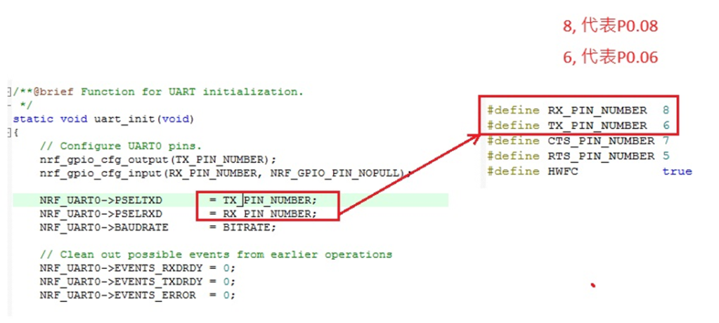
The Bluetooth Association offers a feature for testing RF characteristics. Nordic has incorporated DTM firmware into the SDK according to SIG standard documents. Customers only need to modify the Baud Rate and UART TX/RX pins to conduct RF tests.

1. Download and install nRF Connect for desktop software and nRF5 SDK from the Nordic website.

nRF Connect for desktop download:

https://www.nordicsemi.com/Software-and-tools/Development-Tools/nRF-Connect-for-desktop/Download


nRF5 SDK download:

https://www.nordicsemi.com/Software-and-tools/Software/nRF5-SDK/Download#infotabs


2. Install the Direct Test Mode program in the nRF Connect for desktop software.


3. Extract the SDK package, open the DTM example code from

nRF5_SDK_vxx\examples\dtm\direct_test_mode\ board number\blank, modify TX and RX pins based on the target board's definitions, then compile.

Download the program to the target board connected to the PC.
(Select the appropriate sample code based on the IC/module for testing, referring to the  board number below. )


IC P/Nboard number
NRF52832pca10040
NRF52810pca10040e
NRF52840pca10056
NRF52811pca10056e
NRF52833pca10100
NRF52820pca10100e

RF testing is performed using UART TX/RX commands.
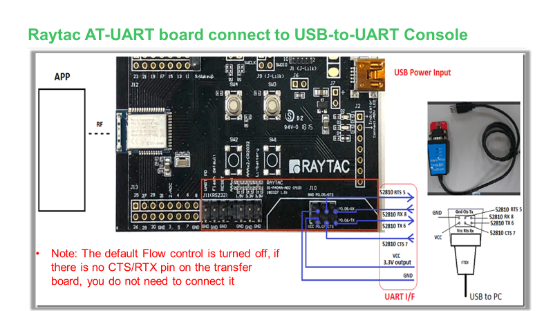
The SDK program defaults to certain positions, but users can modify these two pin positions according to their product design without changing the Baud Rate setting.

UART PinnRF51nRF52
TXDP0.09P0.06
RXDP0.11P0.08


4. Use nRFConnect DTM for testing by adjusting UART TX/RX pins.

Please refer to Video tutorial from link below:
https://github.com/NordicSemiconductor/pc-nrfconnect-dtm/blob/master/resources/screenshot.gif


Radio Test

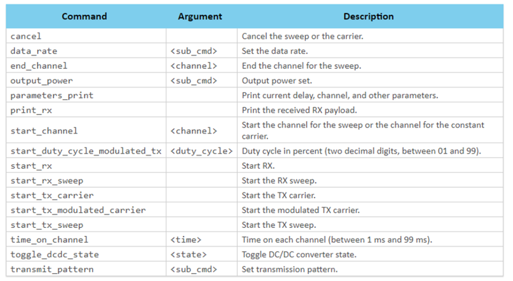
Nordic provides a tool for simpler RF testing, allowing the configuration of radio-related data such as TX power, frequency, TX carrier, and TX modulation carrier through a Command List. It doesn't include testing for RX sensitivity; if needed, users must either write a program for this test or use DTM for testing.

1. Open from nRF5_SDK_vxx\examples\peripheral\radio_test\board number\blank
(Based on the IC/module for testing, referring to the board number below.)

IC P/Nboard number
NRF52832pca10040
NRF52810pca10040e
NRF52840pca10056
NRF52811pca10056e
NRF52833pca10100
NRF52820pca10100e


2. This test also utilizes a Command-based approach to send instructions for different parameter tests. Compared to DTM, Radio Test is more flexible, offering a wider range of RF parameters to test.
The connection method between the target board and PC, serial port modifications, and the approach with DTM are identical.


3. Use the command-Line interface (CLI) through the serial port to control and test the output power, bitrate, and channel settings of the radio parameters during testing.

Additionally, configure the CLI to enable the 32 MHz high-frequency crystal oscillator.

The application allows setting scanning mode with intervals ranging from 1 millisecond to 99 milliseconds (per 1 millisecond) for each channel.


4. Refer to the Nordic CLI commands documentation for the command testing method.

https://infocenter.nordicsemi.com/index.jsp?topic=%2Fcom.nordic.infocenter.sdk5.v15.2.0%2Fnrf_radio_test_example.html&cp=4_0_0_4_5_29_0&anchor=nrf_radio_test_example_commands

5.Testing

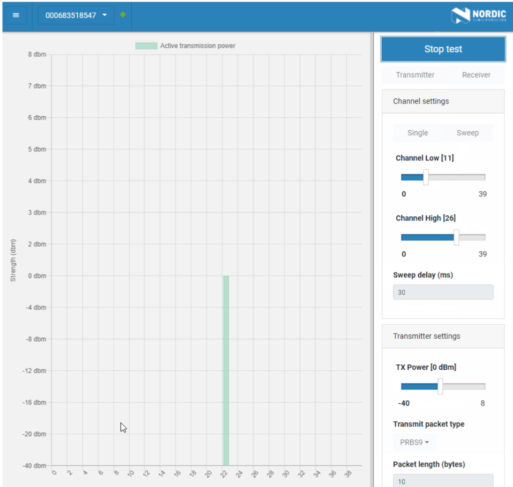
Lastly, we can utilize Spectrum to test PCBA RF characteristics.


Edited by Sales Manager: Ms. Vicky Huang
Raytac Corporation 勁達國際電子有限公司
A BT5.2 & BT5.1 & BT5 module maker based on Nordic nRF53 & nRF52 solution
(nRF5340 & nRF52840 & nRF52833 & nRF52832 & nRF52820 & nRF52811 & nRF528

Wednesday, September 6, 2023

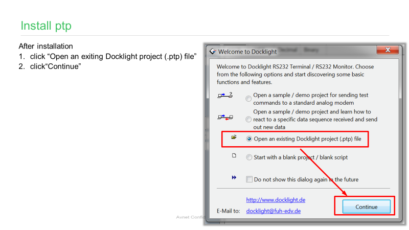
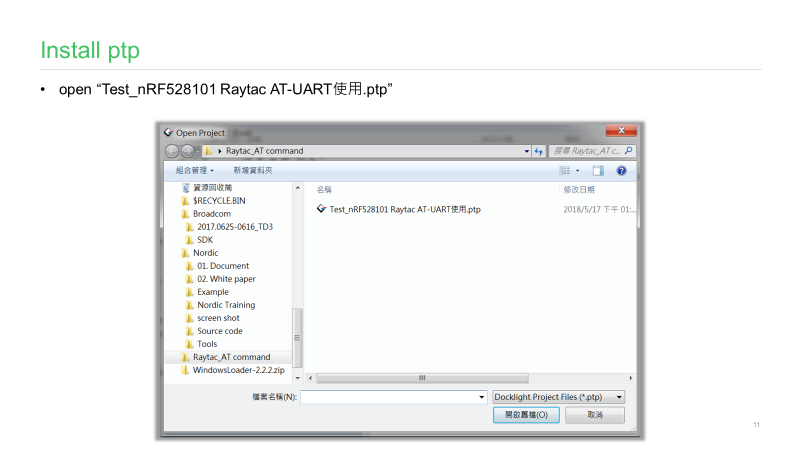
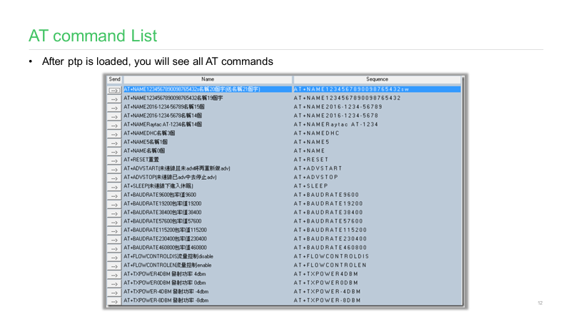
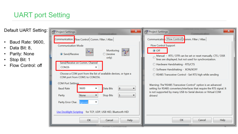
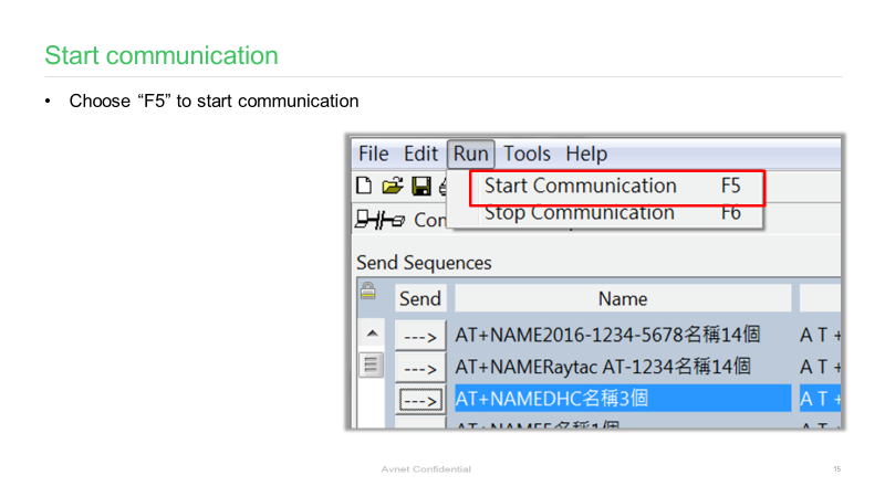
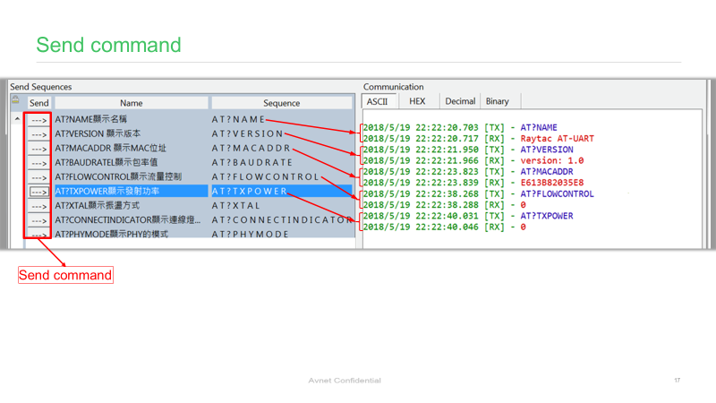
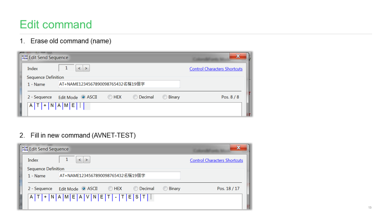
AT Command Tutorial: MDBT42Q-AT/PAT

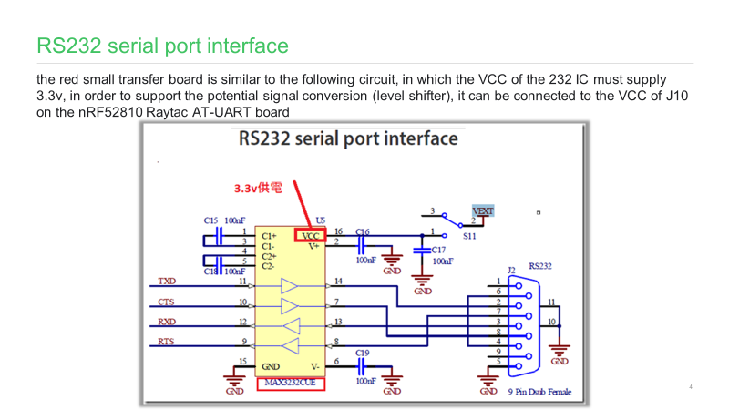
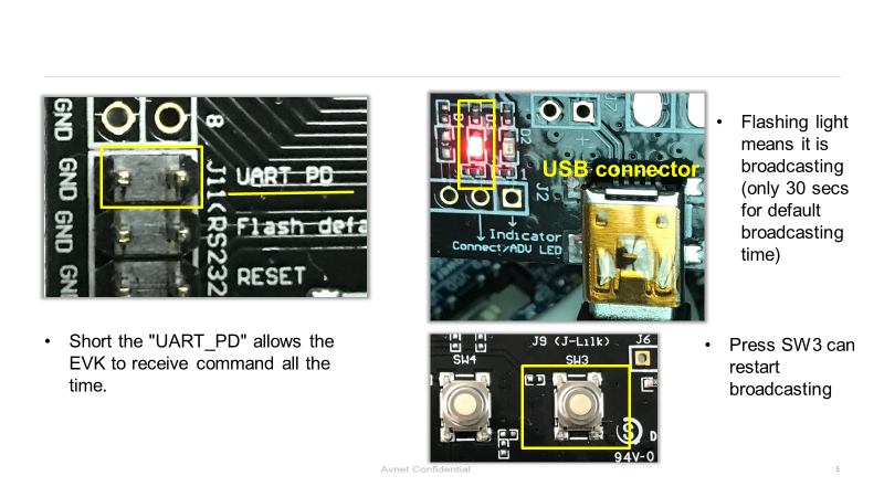
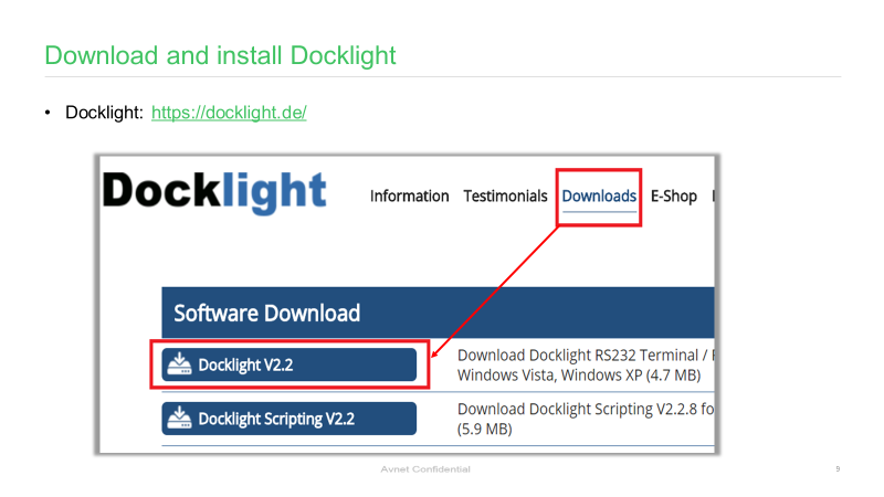
AT commands play a crucial role in wireless communication, IoT, and embedded systems.

This guide aims to assist developers in creating an appropriate environment for efficient AT command usage, ensuring smooth communication and application operation.

Credit to Hanyu Hsu /Avnet Taiwan.

Edited by Sales Manager: Ms. Mandy Chao
Raytac Corporation 勁達國際電子有限公司
A BT5.2 & BT5.1 & BT5 module maker based on Nordic nRF53 & nRF52 solution
(nRF5340 & nRF52840 & nRF52833 & nRF52832 & nRF52820 & nRF52811 & nRF52810 & nRF52805)
http://www.raytac.com email: service@raytac.com Tel: +886.2.3234.0208