Bluetooth modules typically have options for a 32MHz Internal Oscillator (or some called internal crystal oscillator) and a 32.768KHz External Oscillator. The choice between the two is often influenced by specific application requirements, power consumption, accuracy, and cost considerations. Here are some basic differences between Internal and External Oscillators:
Internal Oscillator:(32MHz)
Function: The internal oscillator is embedded within the module and generates the clock signal for the Bluetooth module. This internal oscillator is typically smaller, lightweight, and reduces dependence on external components.
Advantages: Simplifies design, saves space, and reduces costs.
Disadvantages: Some applications may require higher clock stability, which the internal oscillator may not provide to the desired level of precision.
External Oscillator:(32.768KHz)
Function: An external oscillator is an independent oscillator externally connected to the module, offering higher clock stability and accuracy.
Advantages: Provides higher clock stability, suitable for applications with stricter timing requirements.
Disadvantages: Requires additional components, may occupy more space, and increases costs.
Criteria for choosing Internal or External Oscillator:
If the application has modest clock precision requirements, and cost and space are critical factors, choosing the internal oscillator may be suitable.
If the application demands higher timing precision, an external oscillator should be considered for its enhanced clock stability.
Benefits from switching between external and internal oscillator:
Increased Performance Requirements: If the application's performance requirements increase, a higher-precision oscillator, such as an external oscillator, may be needed.
Insufficient Clock Stability: If timing stability issues arise during Bluetooth communication, upgrading to an external oscillator can provide better clock stability.
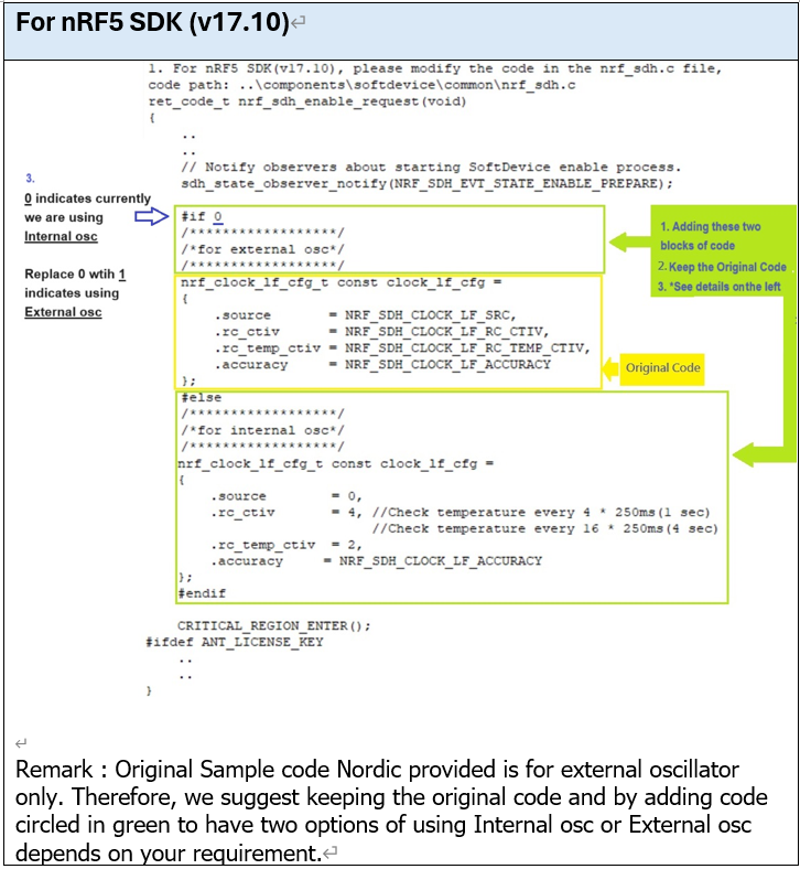
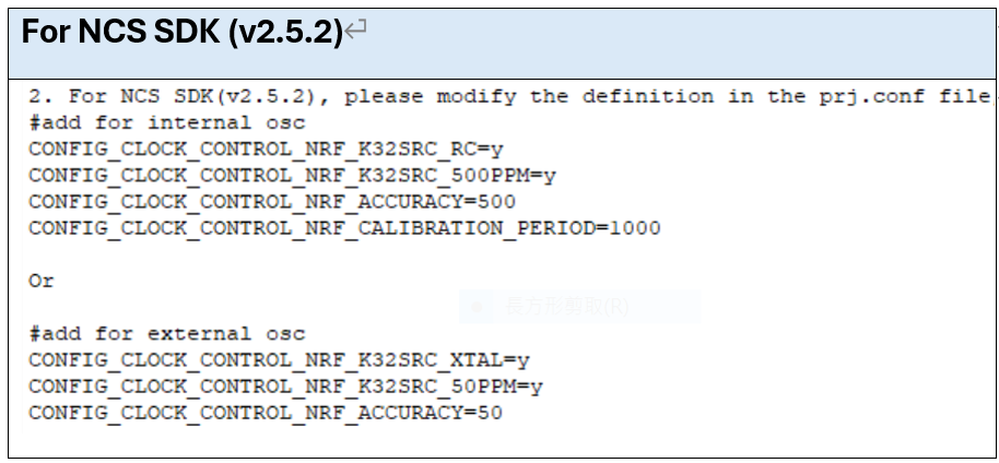
Followings are the instructions we can use to switch between internal oscillator and external oscillator for nRF5 SDK (v17.10) and NCS SDK (v2.5.2).
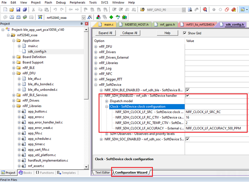
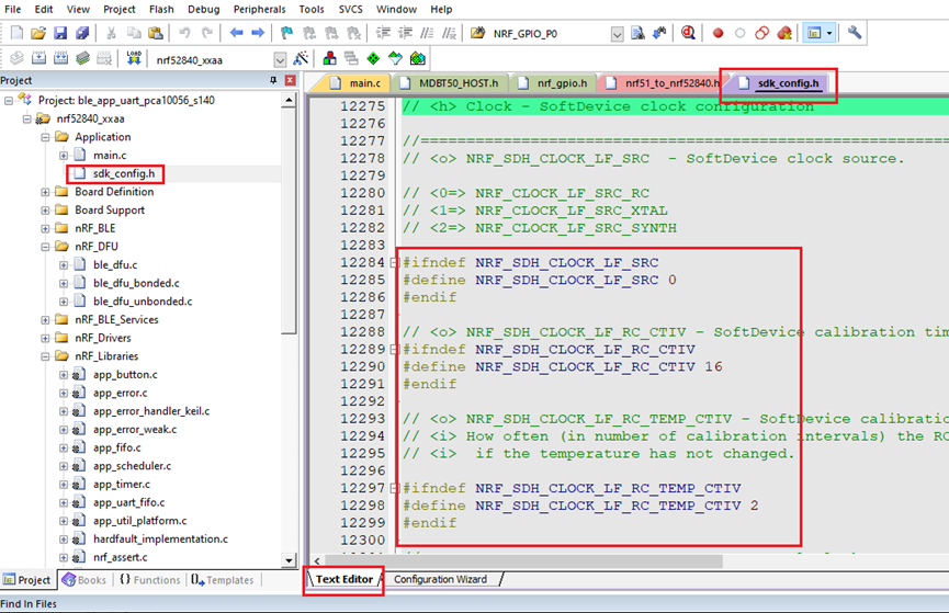
Keil (Keil μVision) and SES (Segger Embedded Studio) are another method commonly used Integrated Development Environments (IDEs) in the field of embedded systems development.
Choosing to use the internal crystal oscillator requires program modifications. Please refer to the following instructions for making these changes in the Keil and SES development environments.
Raytac Corporation, a globally recognized third-party Bluetooth module supplier endorsed by Nordic Semiconductor, has announced a strategic collaboration with Millennium Semiconductor, a specialized electronic agent, starting from November 2023. The establishment of this partnership aims to jointly expand into the Indian market and provide comprehensive services to customers in different regions. Raytac Corporation has consistently focused on the wireless field, earning a reputation as a leading provider of Bluetooth Low Energy modules with outstanding technological capabilities. Additionally, Raytac offers the latest WiFi + BLE modules and a complete range of solutions from Nordic.
The product lineup includes series such as nRF54, nRF5340, nRF52840, nRF52833, nRF52832, nRF52820, nRF52811, nRF52810, nRF52805, nRF51822, all of which have obtained qualifications for BT5.4, BT5.3, BT5.2, and BT5.1. Furthermore, the nRF7002 represents the first device in our array of distinct Wi-Fi products, seamlessly combining with Nordic's established ultra-low power technologies. Raytac Corporation's modules have received Bluetooth (QDID/DID/BQB) and regulatory certifications from various countries and regions, including FCC (USA), CE (Europe), IC (Canada),TELEC (Japan), KC (Korea), SRRC (China), NCC (Taiwan), RCM (Australia/New Zealand), and others.
In addition to delivering excellent performance and transmission distances, Raytac Corporation's modules are relatively compact in size, offering a diverse range of module series choices. This flexibility empowers developers to design without being constrained by module dimensions. Furthermore, the inclusion of AT Command by Raytac facilitates a quick entry for developers into the realms of Bluetooth and the Internet of Things.
Millennium Semiconductors India Private Limited,
17/18/19, 2nd Floor, Mahalaxmi Heights, Mumbai-Pune Road, Pimpri, Pune 411 018, Maharashtra, INDIA.
When launching new products, there is a requirement for RF testing, and two methods are commonly used:
DTM (Direct Test Mode) and Radio Test.
Nordic's SDK provides two RF testing programs: DTM (Direct Test Mode) and Radio Test. While both methods can test RF indicators, they have some distinctions. DTM follows the Bluetooth specification's Direct Test Mode data format (referenced in Bluetooth Core Specification Version 5.2, Vol. 6, Part F.), primarily for Bluetooth certification tests.
On the other hand, Radio Test focuses on the chip's radio indicators, making it more suitable for FCC and ETSI certifications.
Let's delve into detailed explanations for DTM and Radio Test programs.
DTM(Direct Test Mode)
The Bluetooth Association offers a feature for testing RF characteristics. Nordic has incorporated DTM firmware into the SDK according to SIG standard documents. Customers only need to modify the Baud Rate and UART TX/RX pins to conduct RF tests.
1. Download and install nRF Connect for desktop software and nRF5 SDK from the Nordic website.
2. Install the Direct Test Mode program in the nRF Connect for desktop software.
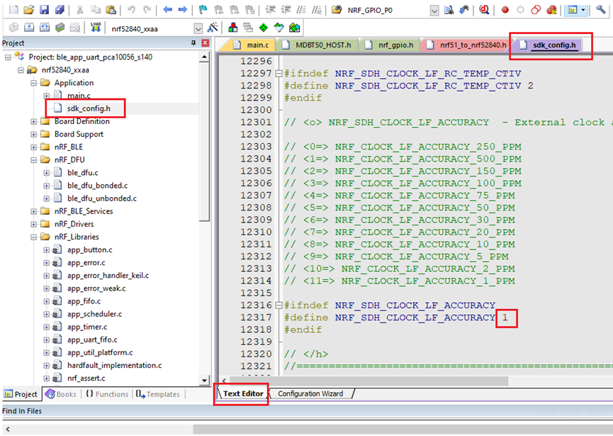
3. Extract the SDK package, open the DTM example code from
nRF5_SDK_vxx\examples\dtm\direct_test_mode\ board number\blank, modify TX and RX pins based on the target board's definitions, then compile.
Download the program to the target board connected to the PC. (Select the appropriate sample code based on the IC/module for testing, referring to the board numberbelow. )
IC P/N
board number
NRF52832
pca10040
NRF52810
pca10040e
NRF52840
pca10056
NRF52811
pca10056e
NRF52833
pca10100
NRF52820
pca10100e
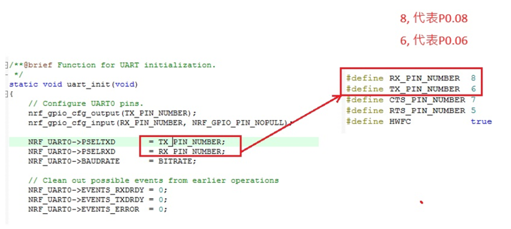
RF testing is performed using UART TX/RX commands. The SDK program defaults to certain positions, but users can modify these two pin positions according to their product design without changing the Baud Rate setting.
UART Pin
nRF51
nRF52
TXD
P0.09
P0.06
RXD
P0.11
P0.08
4. Use nRFConnect DTM for testing by adjusting UART TX/RX pins.
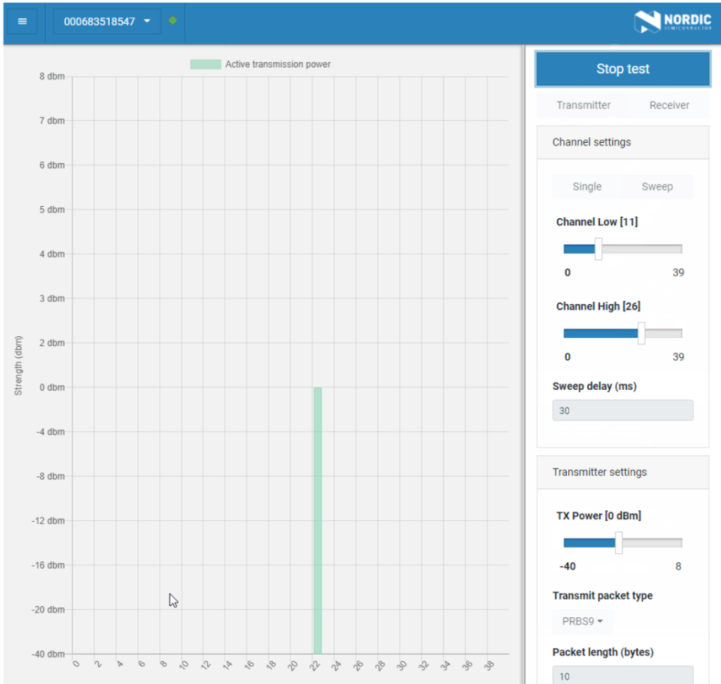
Nordic provides a tool for simpler RF testing, allowing the configuration of radio-related data such as TX power, frequency, TX carrier, and TX modulation carrier through a Command List. It doesn't include testing for RX sensitivity; if needed, users must either write a program for this test or use DTM for testing.
1. Open from nRF5_SDK_vxx\examples\peripheral\radio_test\board number\blank (Based on the IC/module for testing, referring to the board number below.)
IC P/N
board number
NRF52832
pca10040
NRF52810
pca10040e
NRF52840
pca10056
NRF52811
pca10056e
NRF52833
pca10100
NRF52820
pca10100e
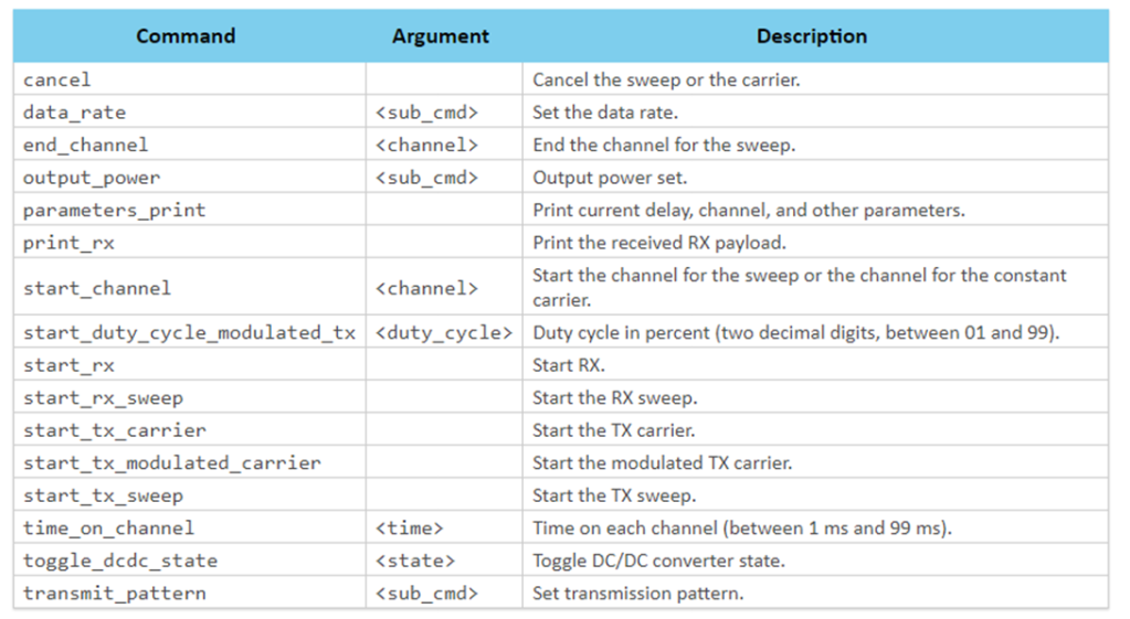
2. This test also utilizes a Command-based approach to send instructions for different parameter tests. Compared to DTM, Radio Test is more flexible, offering a wider range of RF parameters to test. The connection method between the target board and PC, serial port modifications, and the approach with DTM are identical.
3. Use the command-Line interface (CLI) through the serial port to control and test the output power, bitrate, and channel settings of the radio parameters during testing.
Additionally, configure the CLI to enable the 32 MHz high-frequency crystal oscillator.
The application allows setting scanning mode with intervals ranging from 1 millisecond to 99 milliseconds (per 1 millisecond) for each channel.
4. Refer to the Nordic CLI commands documentation for the command testing method.
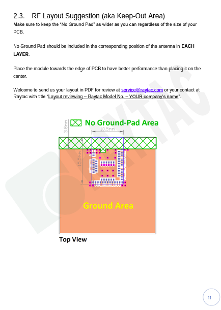
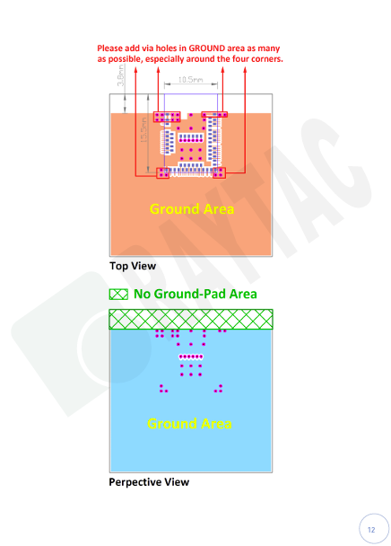
The "keep out area" in a module, particularly when it comes to electronics and antennas, serves several critical purposes:
Electromagnetic Isolation: One of the primary functions of the keep out area is to maintain electromagnetic isolation. It ensures that other components, conductive traces, or structures are not placed too close to the antenna. This is vital to prevent interference and maintain the antenna’s radiation pattern and performance.
Preventing Mutual Interference: Electronic components, especially those generating electromagnetic radiation, can interfere with the antenna’s operation if placed too closely. The keep out area enforces a minimum distance to prevent such interference and maintain the antenna’s signal quality.
Optimizing Radiation pattern: Antennas have specific radiation patterns that dictate how they transmit and received signals. The keep out area helps ensure that the antenna’s radiation pattern remains unobstructed. Placing components within this area can alter the pattern and reduce antenna efficiency.
Safety and Compliance: Compliance with safety and regulatory standards is crucial in electronic devices. The keep out area may be mandated by these standards to minimize the risk of electromagnetic exposure for users and to ensure the device operates within allowable limits.
Thermal Considerations: Some components generate heat during operation. The keep out area can also account for thermal considerations, ensuring that heat-producing components do not adversely affect the antenna's performance due to temperature-induced changes in materials or interference.
Mechanical Clearance: Besides electromagnetic concerns, the keep out area can also provide mechanical clearance, ensuring that the antenna is not physically obstructed by other components or structures.
In summary, the keep out area in a module is a critical design aspect that aims to maintain the integrity, performance, and safety of the antenna system within an electronic device by managing electromagnetic, thermal, mechanical, and regulatory considerations.
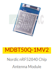
Use following module as our example, you are recommend referring to our specification link on page 12-13forRF layout suggestions (Keep out area.)
Footprint (compatible for Protel, Eagle, Altium Design)
2D/3D drawing
Reflow/Solder Profile
Spec for external 32.768KHz
Instruction to find out selected module’s specific/design guide etc:
Following below steps after link to Raytac Corporation official webpage, click on yellow highlighted texts to find and download selected module’s specific/design guide etc … accordingly.
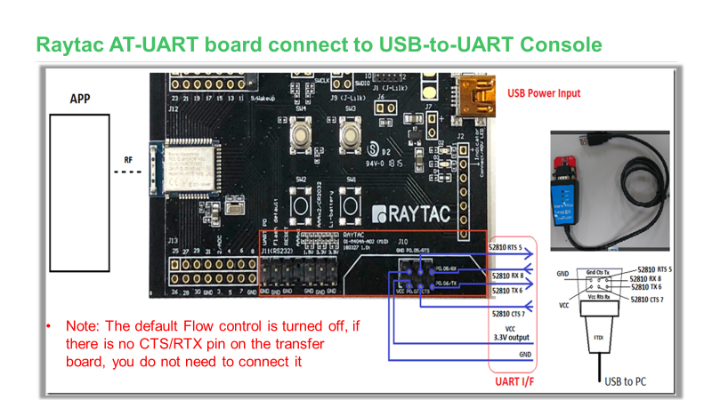
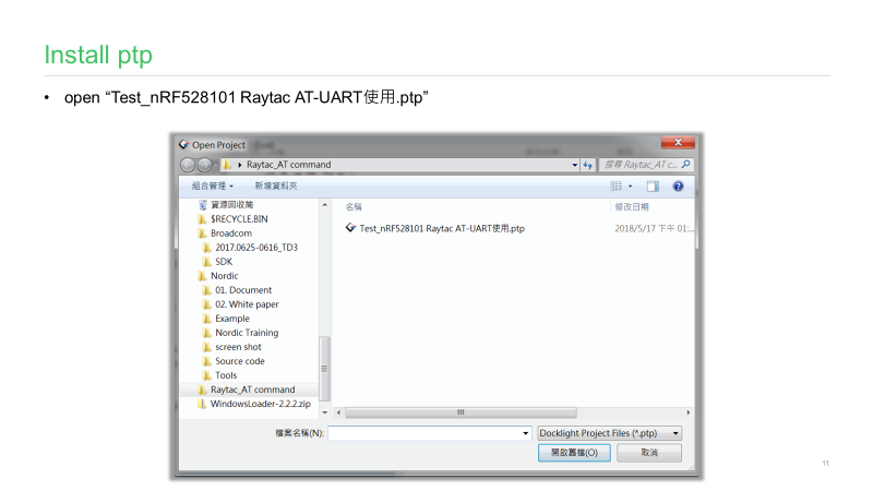
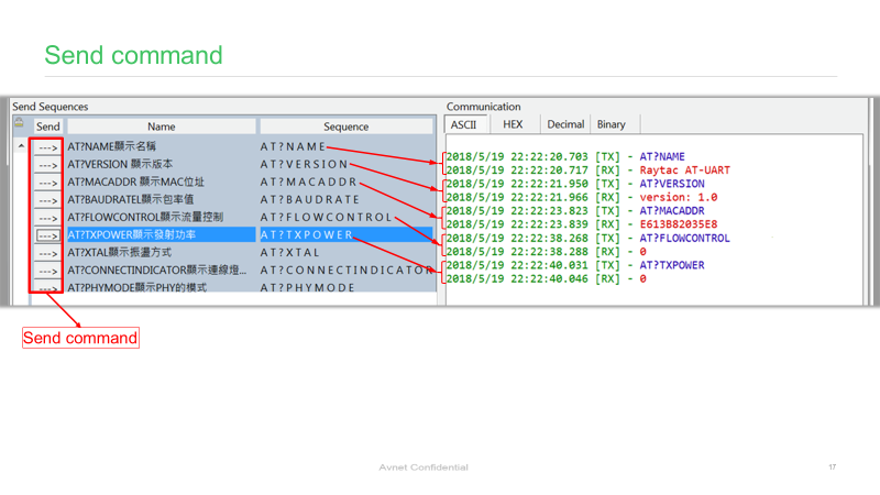
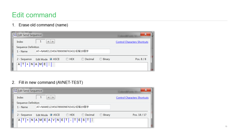
AT commands play a crucial role in wireless communication, IoT, and embedded systems.
This guide aims to assist developers in creating an appropriate environment for efficient AT command usage, ensuring smooth communication and application operation.
SRRC, or the State Radio Regulation Committee, is a mandatory certification required by the National Radio Management Committee of the Ministry of Industry and Information Technology of China. All wireless products sold within China must obtain certification, commonly referred to as SRRC certification, which involves approval of the wireless transmission equipment model.
SRRC Document No. 129:
Document No. 129 introduces various interference avoidance technical requirements for wireless transmission equipment, including "pre-transmission scanning," "monitoring and avoidance," and "Medium Utilization (MU)" for equivalent occupancy rate.
a. "Pre-transmission scanning" and "monitoring and avoidance" mechanisms involve monitoring and listening to the wireless channel before or during signal transmission. By setting appropriate detection threshold levels, the channel's occupancy status is determined to select an idle channel for access.
b. The "equivalent occupancy rate" mechanism requires wireless transmission equipment to self-adjust based on parameters such as "Duty Cycle" and "transmission power," ensuring the "equivalent occupancy rate" remains at a lower level (not exceeding 10%).
1. Certificate Validity Period: Enforced from October 15, 2023. During this period, both old and new policies can be applied. Certificates obtained under the old regulation (Document No. 353) are valid until December 31, 2025. However, certificates obtained by complying with the requirements of Document No. 129 will be valid for 5 years.
2. Sample Requirements: 2.1 The quantity of conducted samples prepared according to the old regulation remains unchanged: 5 samples. 2.2 The major change introduced by Document No. 129 is the addition of interference avoidance technical requirements. The interference avoidance test items include: 1. Maximum channel occupancy time 2. Minimum channel idle time 3. Minimum silence period duration 4. Detection of unused signals 5. Detection threshold 6. Short control signal duty cycle 7. Equivalent occupancy rate.
Differences between Old and New Regulations:
Edited by Sales Manager: Ms. Vicky Huang Raytac Corporation 勁達國際電子有限公司 A BT5.2 & BT5.1 & BT5 module maker based on Nordic nRF53 & nRF52 so
Thread Group(https://www.threadgroup.org/)Founded on July 15, 2014 by Apple, Amazon, Google and six companies member. As a non-profit organization, Thread Group focuses on promoting the application of Thread in the field of Internet of Things, training developers and consumers, introducing thread technology and its advantages, and providing strict product certification tests to ensure the optimized user experience.
What is Thread?
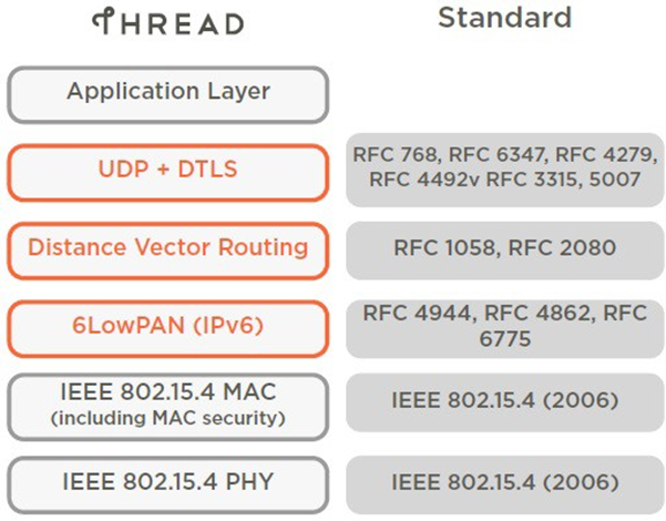
Thread is a secure wireless mesh networking protocol. Thread solving new needs that in building a network of smart home products. Thread is based on 6LoWPAN of structure, making full use of open standards and IPv6 technology. Compared with other wireless standards, Thread has many technical advantages: safe and reliable, no single point connection failure in network, more simple connection, and low power consumption. Product developers and consumers can easily and securely form more than 250 devices into a low-power wireless Mesh network through Thread, and each device in the network can connect to the Internet and access cloud services. The Thread protocol stack is an open standard built on a series of existing standards of the Institute of Electrical and Electronics Engineers (IEEE) and the Internet Engineering Task Force (IETF), rather than a new standard (see the figure below).
Figure 1. Overview of the Thread protocol stack
General characteristics of Thread
The Thread protocol stack supports IPv6 addresses, and it can realize low-cost bridging with other IP networks. It is the best choice for low-power/battery-powered operation and communication between wireless devices. The Thread protocol stack is designed for smart home and business applications based on IP networks and can be matched with various application layers on the protocol stack.
The general characteristics of the Thread protocol stack are as follows:
• Simple and convenient network installation, start-up, and operation: Thread protocol stack supports various network topologies. It can be installed via smartphone, tablet or computer, and the installation is simple and convenient. Product installation codes ensure that only authorized devices can join the network. When arise out of routing problems, simple protocols for building and joining networks enable the system to configure itself and fix those problems.
• Security: Devices cannot join the network unless authorized, and all communications are encrypted and protected. Security protection can be used at the network layer as well as at the application layer. All Thread networks are encrypted with an authentication scheme and Advanced Encryption Standard (AES). The Thread network is more secure than any other wireless network the Thread Group has evaluated.
• Can accommodate the needs of home networks of various sizes: The number of devices in different home networks varies greatly, ranging from a few to hundreds. Network layer design aims to optimize network operation for its intended use.
• Applicable to large commercial networks: For large commercial networks, a single Thread network is not enough to meet the requirements of all applications, systems and networks. The Thread domain model allows scaling up to 10,000 Thread devices in a single deployment, achieved through the combined use of different connectivity technologies (Thread, Ethernet, Wi-Fi, etc.).
• Two-way communication for service discovery and connection: Multicast and broadcast are inefficient for wireless mesh networks. For communication with the outside world of the Mesh network, Thread provides a communication registration service, and the device can register whether it is available and whether it can provide communication services, and the client can use unicast queries to find registered services.
• Wide coverage: The coverage of a typical Thread device is usually sufficient for the average household. A design with a power amplifier can greatly improve coverage. In the physical layer (PHY), the distributed spread spectrum technology can better improve the anti-interference ability. For commercial networks, the Thread domain model allows multiple Thread networks to communicate with each other through the backbone network, so it can be expanded to cover multiple Mesh subnets.
•Designed with no single point of failure: The Thread protocol stack is designed to operate safely and reliably, even in the event of a single device failure or absence. Thread devices can also incorporate IPv6-based links (such as Wi-Fi and Ethernet) into the topology to reduce the possibility of multiple Thread partitions. This allows Thread devices to take advantage of the higher throughput, greater channel capacity and wider coverage of these infrastructure links, while still supporting low-power devices.
• Low Power Consumption: Devices communicate efficiently and have an expected lifetime of several years under normal battery usage, resulting in an improved user experience. With the right duty cycle, the device can typically run for years on AA-size batteries.
• Cost-effective: Compatible chipsets and software stacks from multiple vendors are priced for mass deployment and designed for ultra-low power consumption.
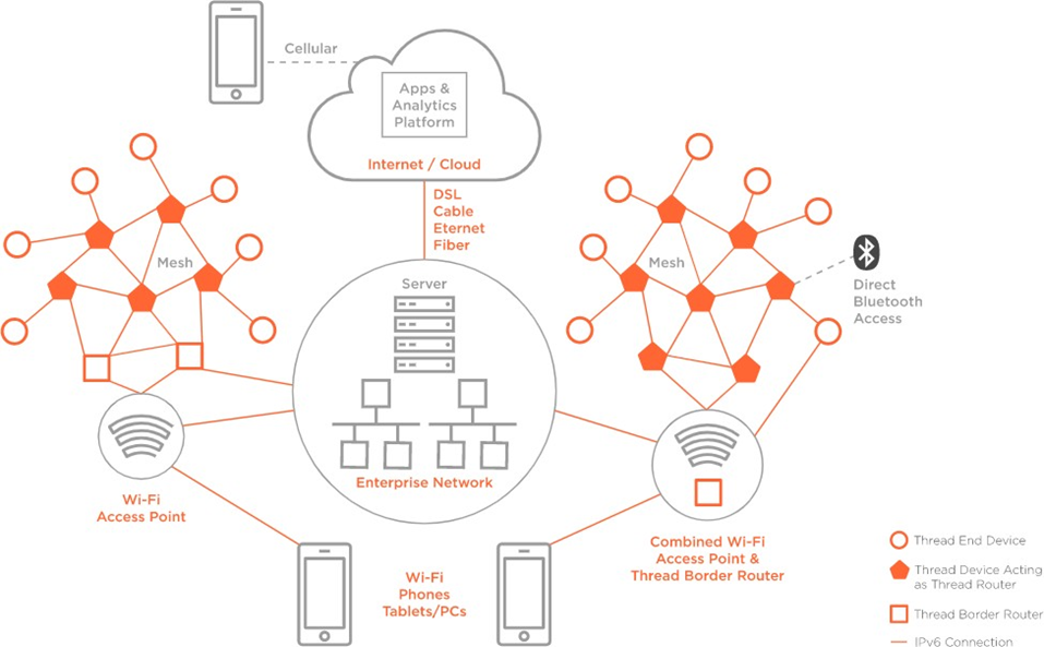
Thread home network architecture
Users communicate with the home Thread network via Wi-Fi on their home area network (HAN) or from their own device (smartphone, tablets or computer) using a cloud-based application. The figure below illustrates the main device types in the Thread network architecture.
Figure 2. Thread home network architecture
• Border Router: supports the network connection between the 802.15.4 network and other adjacent physical layers (Wi-Fi, Ethernet, etc.). The border router provides services for devices in the 802.15.4 network, including routing services and service search in the case of offline operation. There can be one or more border routers in a Thread network.
• Leader: located in the Thread network, responsible for managing the allocation and registration of router IDs, and accepting requests from terminal devices (REEDs) that meet the requirements of routers to become routers. The Leader decides which devices should be routers, and, like all routers in the Thread network, the Leader can also have sub-devices. Leader also assigns and manages router addresses through CoAP (Constrained Application Protocol). However, all information contained in the Leader is also stored in other Thread routers. Therefore, if the Leader fails or loses connection to the Thread network, another Thread router can be elected as the Leader without user intervention.
• Thread Router: Provides routing services for network devices. Thread routers also provide joining and security services for devices attempting to join the network. Thread routers cannot sleep and can also be REED by downgrading their functionality.
• REED: It can be a Thread router or a Leader, but not necessarily a border router with special attributes (such as multiple interfaces). Depending on the network topology or other specific circumstances, REED cannot be a router. REED does not relay messages, nor does it provide joining or security services to other devices on the network. If necessary, the network manages router-eligible devices and upgrades them to routers without user intervention.
• End Device: The end device that does not meet the router conditions can be FED (full end device) or MED (minimum end device). The MED does not need to be synchronized with the parent device to communicate.
• Sleepy End Device (SED): communicates only through the Thread router parent device and cannot relay messages for other devices.
• Synchronous Sleeping End Device (SSED): A type of Sleeping End Device that uses CSL in IEEE 802.15.4-2015 to keep synchronized with a parent device without using regular data requests.
Thread business network architecture
The Thread business networking model takes the same major device types as home networking and introduces new concepts. Users communicate with the business network through devices (smartphones, tablets, or computers) via Wi-Fi or the corporate network. The following figure illustrates the business network topology.
Figure 3. Thread business network architecture
Concept of business network architecture:
• The Thread domain model supports seamless integration of multiple Thread networks, and also supports seamless connection with non-Thread IPv6 networks. The main advantage of the Thread domain is that the device can flexibly join the available Thread network configured with the public Thread domain to a certain extent, and when the network scale expands or the data volume expands, this will reduce the manual planning of the network or reduce the cost of High costs for manual reconfiguration.
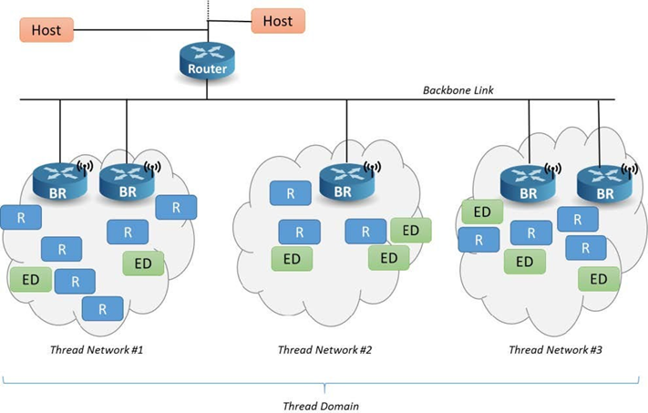
• Backbone Border Router (BBR) is a kind of border router used in commercial networks, it can promote the synchronization of Thread domains in multiple network sagments, and allow large-scale multicast transmission in and out of each individual network in the Thread domain. Thread networks that are part of a larger domain must have at least one "primary" BBR, and can have multiple "secondary" BBRs for failsafe redundancy. Each BBR communicates with each other through the backbone network connecting all Thread networks.
Figure 4. Thread domain model
no single point of failure
The Thread protocol stack is designed to avoid single points of failure. Although there are many devices in the system that perform special functions, the Thread network enables these devices to be replaced without affecting the network or the continued operation of the devices. For example, if a dormant end device needs a parent device to communicate, then that parent device becomes a single point of failure for communication. However, in a Thread network, a dormant end-device can choose another parent when its parent is unavailable. And this conversion process is invisible to the user.
Although the Thread system adopts a no-single-point-of-failure design, in some topologies, individual devices do not have backup functions. For example, in a system configured with a single border router, if the border router loses power, there is no way to fail over to the backup border router. In this case, the border router must be reconfigured.
With Thread Specification 1.3.0, border routers that share infrastructure links can facilitate designs with no single point of failure across media such as Wi-Fi or Ethernet by leveraging Thread Radio Encapsulation Links (TREL). With this function, the possibility of forming Thread partitions across links is reduced.


