
RF Test – DTM & Radio Test
When launching new products, there is a requirement for RF testing, and two methods are commonly used:
DTM (Direct Test Mode) and Radio Test.
Nordic's SDK provides two RF testing programs: DTM (Direct Test Mode) and Radio Test. While both methods can test RF indicators, they have some distinctions. DTM follows the Bluetooth specification's Direct Test Mode data format (referenced in Bluetooth Core Specification Version 5.2, Vol. 6, Part F.), primarily for Bluetooth certification tests.
On the other hand, Radio Test focuses on the chip's radio indicators, making it more suitable for FCC and ETSI certifications.
Let's delve into detailed explanations for DTM and Radio Test programs.
DTM(Direct Test Mode)
The Bluetooth Association offers a feature for testing RF characteristics. Nordic has incorporated DTM firmware into the SDK according to SIG standard documents. Customers only need to modify the Baud Rate and UART TX/RX pins to conduct RF tests.
1. Download and install nRF Connect for desktop software and nRF5 SDK from the Nordic website.
nRF Connect for desktop download:
https://www.nordicsemi.com/Software-and-tools/Development-Tools/nRF-Connect-for-desktop/Download
nRF5 SDK download:
https://www.nordicsemi.com/Software-and-tools/Software/nRF5-SDK/Download#infotabs
2. Install the Direct Test Mode program in the nRF Connect for desktop software.

3. Extract the SDK package, open the DTM example code from
nRF5_SDK_vxx\examples\dtm\direct_test_mode\ board number\blank, modify TX and RX pins based on the target board's definitions, then compile.
Download the program to the target board connected to the PC.
(Select the appropriate sample code based on the IC/module for testing, referring to the board number below. )
| IC P/N | board number |
| NRF52832 | pca10040 |
| NRF52810 | pca10040e |
| NRF52840 | pca10056 |
| NRF52811 | pca10056e |
| NRF52833 | pca10100 |
| NRF52820 | pca10100e |
RF testing is performed using UART TX/RX commands.
The SDK program defaults to certain positions, but users can modify these two pin positions according to their product design without changing the Baud Rate setting.
| UART Pin | nRF51 | nRF52 |
| TXD | P0.09 | P0.06 |
| RXD | P0.11 | P0.08 |
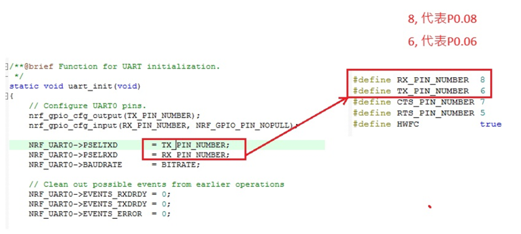
4. Use nRFConnect DTM for testing by adjusting UART TX/RX pins.
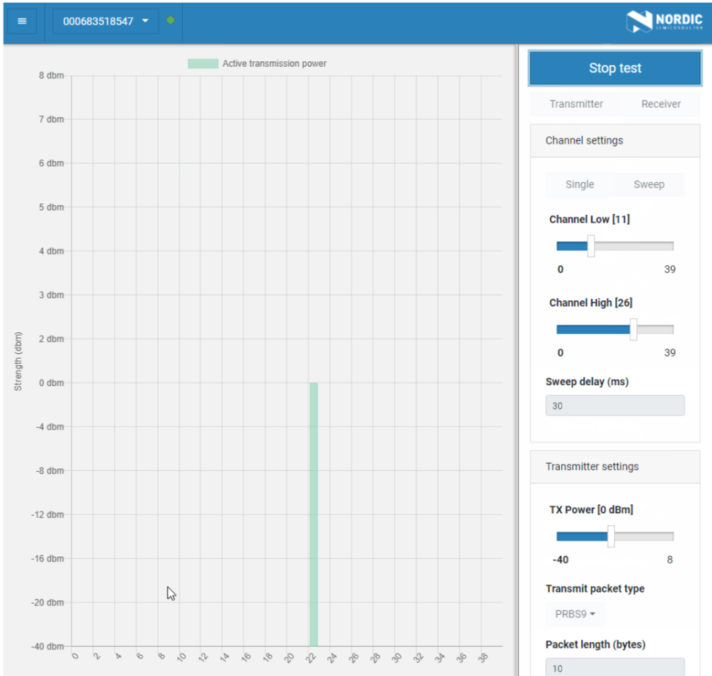
Please refer to Video tutorial from link below:
https://github.com/NordicSemiconductor/pc-nrfconnect-dtm/blob/master/resources/screenshot.gif
Radio Test
Nordic provides a tool for simpler RF testing, allowing the configuration of radio-related data such as TX power, frequency, TX carrier, and TX modulation carrier through a Command List. It doesn't include testing for RX sensitivity; if needed, users must either write a program for this test or use DTM for testing.
1. Open from nRF5_SDK_vxx\examples\peripheral\radio_test\board number\blank
(Based on the IC/module for testing, referring to the board number below.)
| IC P/N | board number |
| NRF52832 | pca10040 |
| NRF52810 | pca10040e |
| NRF52840 | pca10056 |
| NRF52811 | pca10056e |
| NRF52833 | pca10100 |
| NRF52820 | pca10100e |
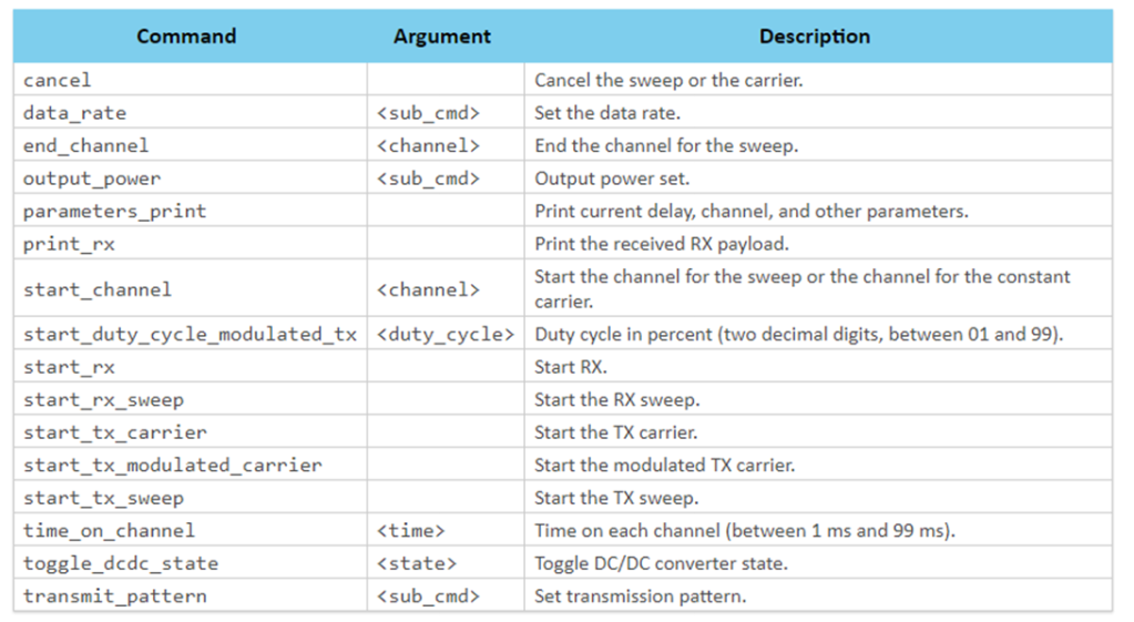
2. This test also utilizes a Command-based approach to send instructions for different parameter tests. Compared to DTM, Radio Test is more flexible, offering a wider range of RF parameters to test.
The connection method between the target board and PC, serial port modifications, and the approach with DTM are identical.
3. Use the command-Line interface (CLI) through the serial port to control and test the output power, bitrate, and channel settings of the radio parameters during testing.
Additionally, configure the CLI to enable the 32 MHz high-frequency crystal oscillator.
The application allows setting scanning mode with intervals ranging from 1 millisecond to 99 milliseconds (per 1 millisecond) for each channel.
4. Refer to the Nordic CLI commands documentation for the command testing method.
5.Testing
Lastly, we can utilize Spectrum to test PCBA RF characteristics.

Edited by Sales Manager: Ms. Vicky Huang
Raytac Corporation 勁達國際電子有限公司
A BT5.2 & BT5.1 & BT5 module maker based on Nordic nRF53 & nRF52 solution
(nRF5340 & nRF52840 & nRF52833 & nRF52832 & nRF52820 & nRF52811 & nRF528