The supplier(of the original chip antenna) notified Raytac in March 2026 that the original chip antenna has reached its end-of-life (EOL) status, thus the introduction of an alternative(new) chip antenna from the same supplier to ensure long term supply continuity.
There are no changes on Form, Fit, Function, and Quality of Reliability. Only change in Chip Antenna Appearance.
Upon receiving this notice, our R&D team promptly conducted comprehensive validation. The results confirm that there is no impact on RF performance, EMC compliance, or related certifications.
In conclusion, all existing certifications and technical documentations remain valid.
The change is already effective as the existing inventory of the original chip antenna has been depleted. All production batches are already using the new chip antenna.
We kindly invite our customers, distributors, and partners to update your records accordingly. For any questions or support, and further document requests regarding this update, feel free to reach out to Raytac Sales Team via: sales@raytac.com.
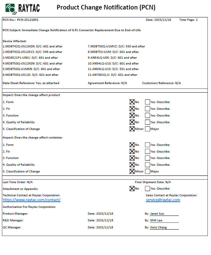
There are no changes on Form, Fit, Function, and Quality of Reliability. Only change in u.FL Connector Appearance. All existing certifications and technical documentations remain valid.
We kindly invite our customers, distributors, and partners to update your records accordingly. For any questions or support regarding this update, feel free to reach out via: sales@raytac.com.
The "keep out area" in a module, particularly when it comes to electronics and antennas, serves several critical purposes:
Electromagnetic Isolation: One of the primary functions of the keep out area is to maintain electromagnetic isolation. It ensures that other components, conductive traces, or structures are not placed too close to the antenna. This is vital to prevent interference and maintain the antenna’s radiation pattern and performance.
Preventing Mutual Interference: Electronic components, especially those generating electromagnetic radiation, can interfere with the antenna’s operation if placed too closely. The keep out area enforces a minimum distance to prevent such interference and maintain the antenna’s signal quality.
Optimizing Radiation pattern: Antennas have specific radiation patterns that dictate how they transmit and received signals. The keep out area helps ensure that the antenna’s radiation pattern remains unobstructed. Placing components within this area can alter the pattern and reduce antenna efficiency.
Safety and Compliance: Compliance with safety and regulatory standards is crucial in electronic devices. The keep out area may be mandated by these standards to minimize the risk of electromagnetic exposure for users and to ensure the device operates within allowable limits.
Thermal Considerations: Some components generate heat during operation. The keep out area can also account for thermal considerations, ensuring that heat-producing components do not adversely affect the antenna's performance due to temperature-induced changes in materials or interference.
Mechanical Clearance: Besides electromagnetic concerns, the keep out area can also provide mechanical clearance, ensuring that the antenna is not physically obstructed by other components or structures.
In summary, the keep out area in a module is a critical design aspect that aims to maintain the integrity, performance, and safety of the antenna system within an electronic device by managing electromagnetic, thermal, mechanical, and regulatory considerations.
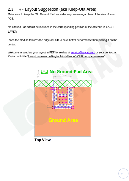
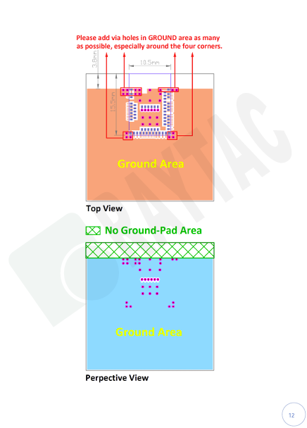
Use following module as our example, you are recommend referring to our specification link on page 12-13forRF layout suggestions (Keep out area.)
Footprint (compatible for Protel, Eagle, Altium Design)
2D/3D drawing
Reflow/Solder Profile
Spec for external 32.768KHz
Instruction to find out selected module’s specific/design guide etc:
Following below steps after link to Raytac Corporation official webpage, click on yellow highlighted texts to find and download selected module’s specific/design guide etc … accordingly.
Raytac today announces the u.FL connector version module, MDBT42Q-U series which selects Nordic nRF52832 and nRF52810 SoC to provide the Bluetooth Low Energy (Bluetooth LE, aka BLE) wireless connectivity for IoT applications.
Raytac's EE policy (Easy Employee) core is to provide the pre-certified modules.
Benefits from this policy, products built by Raytac's module may save or reduce the procedure in certification application process which successfully improved Time To Market efficiency and Cost Effective for all customers.
Raytac's latest module, MDBT50Q series module employed Nordic nRF52840 solution has developed 3 lines with different antenna type.
MDBT50Q-1M: Chip Antenna
MDBT50Q-P1M: PCB Antenna
MDBT50Q-U1M: u.FL connector with external Antenna.
We are glad to announce that MDBT50Q series modules have FCC Part 15 C Regulation Certificated granted with FCC ID: SH6MDBT50Q.
FCC Category: Portable Device
Product Name: Bluetooth Low Energy & IEEE802.15.4 Combo Module
Certified Protocol : BT5 & IEEE 802.15.4
Certification Detail
Certification Item
MDBT50Q-1M (Chip Antenna Version)
MDBT50Q-P1M (PCB Antenna Version)
MDBT50Q-U1M (External Antenna Version, Listed in below)
Raytac Corporation 勁達國際電子有限公司
A BT4.1 & BT 4.2 & BT 5.0 module maker based on Nordic nRF51 & nRF52 solution


.png)