Showing posts with label Debug. Show all posts

Wednesday, June 17, 2026

User Manual of Raytac AN54LV-DB-15 (Nordic nRF54L15 Module DevKit) Development & Programming Environment

Want to get started quickly with Raytac's AN54LV-15 module? We provide a simple tutorial to guide you step-by-step through setting up the development and programming environment for the nRF54L15 module Development Board (AN54LV-DB-15) and nRF54L15-DK.


Table of Contents
1. Hardware Environment Setup
2. Software Development Kit Resources and Environment Setup
3. Software/Firmware Application Development
4. Flashing / Programming

Related products:
nRF54L15 SoC Spec  << access link
Nordic nRF54L15 DK  << access link
Raytac AN54LV-DB-15 (Development Kit used in this article) << access link
Zephyr documentation of AN54LV-DB-15 << access link
Raytac AN54LV-DB-U15 (Development Kit with u.FL Connector for external antenna) << access link
Raytac AN54LV-DB-K15 (Development Kit with antenna pin) << access link

User manual of Raytac AN54LQ-DB-15 << access linkNordic nRF54L15-DK


1. Hardware Environment Setup
The required equipments are as follows:

  • 1 x Nordic nRF54L15-DK: PCA10156(1.0.0)
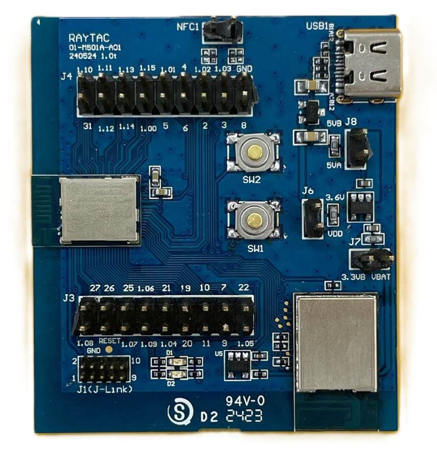
  • 1 x AN54LV-DB-15 (Raytac nRF54L15 module Development Board)
  • 1 x IDC Ribbon Cable
  • 2 x USB Type-C Connection Cables

* Reminder: The "Nordic nRF54L15-DK" and "Raytac AN54LV-DB-15 Development Board" must be used together to proceed with application development and flashing firmware into the Raytac AN54LV-DB-15 development board.

Setup Steps:
Step 1: Connect the J-Link on the Nordic DK with the AN54LV-DB-15 using the IDC ribbon cable.


Make sure to match the red side of the IDC ribbon cable with "1" printed on the AN54LV-DB-15's J-Link socket.


Step 2: Use the Type-C USB cables to supply power to both the nRF54L15-DK and the AN54LV-DB-15.


The outcome should be same as the picture above.

Step 3: AN54LV-DB-15 Schematic(Click on the schematic to zoom in):


2. Software Development Kit Resources and Environment Setup
Software Tool kits & Download Links:
Download nRF Connect for Desktop: Download nRF Connect For Desktop (Please Click Me)
Download nRF Command Line Tools: Download nRF Command Line Tools (Please Click Me)
Download Visual Studio Code(VS Code): Download nRF Command Line Tools (Please Click Me)

Setup Steps:
Step 1: Download the latest version of nRF Connect for Desktop. Choose the Windows 64-bit - version 5.3.1 installer (nrfconnect-setup-5.3.1-x64.exe). Once finished, you will see " nRF Connect for Desktop" on your PC.

Step 2: Download the latest version of nRF Command Line Tools. Choose the Windows X86 64 - version 10.24.2 installer (nrf-command-line-tools-10.24.2-x64.exe)

* Reminder: During the installation of the above two programs, a window may pop up prompting that SEGGER J-LINK needs to be installed or updated concurrently.

If you’re initiating Segger Embedded Studio (SES) application, please check the guideline here(Click me)\


Step 3: Download the latest version of Visual Studio Code (VS Code). Choose Windows VSCodeUserSetup-x64 version 1.122 (VSCodeUserSetup-x64-1.122.1.exe). Once complete, you will see "Visual Studio Code" on your PC.

Step 4: After installation is complete, you can verify the installed packages in your PC's Control Panel under "Programs and Features":


3. Software/Firmware Application Development
You can develop application programs within the VS Code IDE development environment.
Below steps are how to install and select your target SDK version (nRF Connect SDK v3.3.0 in this article):

Step 1: Launch "VS Code"-> Select "nRF Connect" icon/extension on the side menu.


Click "Manage SDKs" and then select "Install SDK".


Step 2: Select "nRF Connect SDK".


Step 3: You will see several available versions of nRF Connect SDK vx.x.x. It is highly recommended to choose and install NCS v3.3.0 or later. In this guide, we select nRF Connect SDK(NCS) v3.3.0.


Step 4: Before starting the download for (NCS)v3.3.0, confirm your preferred target installation pathway.
By default, it is configured to c:\ncs\v3.3.0. Press 'Enter' to confirm.


Step 5: Once the nRF Connect SDK v3.3.0 environment setup finishes successfully, open the Bluetooth sample folder and select the "peripheral_uart" application template, then click "Open".


Step 6: In the "nRF Connect" layout, go to "Applications" --> "Add build configuration".


Under "Board target", look up and select "nrf54l15dk/nrf54l15/cpuapp" --> "Generate and Build".


* Note: You can also choose the board name “raytac_an54lv_db_15/nrf54l15/cpuapp” for subsequent building and development.


After completing the configuration, you will see "Build complete".


Step 7: Compilation completed. Once completed, a binary file named "zephyr.hex" will be generated in your "build" directory.


Step 8: Under the "ACTIONS" interface, you can switch between Build, Debug, and Flash functionalities dynamically.

Build


Debug


Flash


Step 9: CRITICAL BEFORE FLASHING/DEBUGGING: You have to change the VDD voltage configuration on the nRF54L15-DK board to 3.3V.

To do this: Launch "nRF Connect for Desktop" -> choose "Board Configurator" -> click "Open"


Change the VDD target selection value to "3.3V" -> click "Write config".


4. Flashing / Programming
The nRF Connect SDK (NCS) natively supports direct programming.
You can utilize the "Programmer" application tool to flash the compiled zephyr.hex binary file onto the target chip.
The exact procedure is detailed below:

Step 1: Open "nRF Connect for Desktop" -> select "Programmer" and click "Open".


Click "Select Device" and choose "nRF54L15DK".


Click "Add file".


Step 2: Select your compiled target ".hex" file.


Click "Erase & write" to initiate the programming/flashing process.


While flashing, a progress diagonal pattern will display on the right-hand panel.


When the LOG shows a "completed" status text, it means that the programming/flashing is successfully done.


Step 3: After the flash operation completes, you can download the "nRF Connect for Mobile" app to scan and verify that the Raytac AN54LV-DB-15 development board is advertising normally.

"nRF Connect for Mobile" app download link: https://www.nordicsemi.com/Products/Development-tools/nRF-Connect-for-mobile


Useful References
nRF Connect SDK Documentation: https://developer.nordicsemi.com/nRF_Connect_SDK/doc/3.3.0/nrf/index.html

Nordic DevZone(technical support forum): Nordic Devzone for technical issue discussion


Edited by Account Manager: Christine Huang
Technical Guidance by R&D Manager: MW Lee

Raytac Corporation 勁達國際電子股份有限公司 / Raytac Corporation (USA) / abietec Inc.
A Bluetooth, Wi-Fi, and LoRa Module Maker/ODM & OEM Manufacturer based on
Nordic nRF54; nRF53: nRF52; nRF51; nRF7002
Infineon: CYW55912
NXP: RW610, RW612
Semtech: SX1262

Bluetooth Specification: BT6 ; BT5.4 ; BT5.3 ; BT5.2.
Wi-Fi Specification: Wi-Fi 6
LoRa Specification: LoRaWAN
Zephyr Project Silver Member

All products are FCC/IC/CE/Telec/KC/RCM/SRRC/NCC/WPC/RoHS/Reach Pre-Certified.

http://www.raytac.com
https://www.raytac.com/contact/
https://www.abietec.com/
email: sales@raytac.com
Tel: +886-2-3234-0208(TW)/+1-626-328-3827(USA)

Saturday, November 22, 2025

16-Jan-2026 Update: How to set up Hardware & Software, Build & Compile Firmware, Validate DFU, and Wifi SCAN using Raytac’s Nordic nRF7002+nRF5340 WiFi+BLE Devkit-AN7002Q-DB-5340-M

Raytac has advanced the dev kit of bundle offer – WIFI+BLE:
AN7002Q-DB-5340-M with an on-board flash memory(MX25R64) to create easy evaluation for Wi-Fi project developments.

[January 2026 Update]
In this article, we will talk about:
Project WITH External Flash MX25R64(8MB) applied
- Connecting through SPI between nRF5340 module: MDBT53-1M(BLE) & nRF7002 module: AN7002Q(WIFI)
- Connecting through QSPI (XIP) between MDBT53-1M and external memory MX25R64

Table of Content———————————————————————————————

  1. Hardware Set Up
    A. Project WITHOUT External Flash MX25R64 needed
    B. Project WITH External Flash MX25R64 needed
  2. Software Resources & Preparations
  3. Firmware Build & Compile
    A. Project WITHOUT External Flash MX25R64 needed
    B. Project WITH External Flash MX25R64 needed
  4. Validate DFU Process & WIFI SCAN

——————————————————————————————————————


1. Hardware Set Up

Hardware Kit on hand:

Note: Pease make sure to have both “Nordic nRF5340-DK” and “AN7002Q-DB-5340-M” connected and running during the WIFI+BLE (nRF7002+nRF5340) project development.

Hardware Network:
IDC Ribbon Wire(J-Link Cable): Connect nRF5340-DK to AN7002Q-DB-5340-M
USB Wire –Type C USB: Power supply to AN7002Q-DB-5340-M through USB TYPE-C
USB Wire-Micro USB: Power supply to nRF5340-DK through Micro USB


Schematic diagram of AN7002Q-DB-5340-M can be referenced for design as follows.

(Click on the image to zoom in.)

*nRF7002 module <- SPI -> nRF5340 module
*MX256R NOR Flahs <-QSPI-> nRF7002 module


!! Important Note:!!

The circuit of SW1(p1.08)/SW2(p1.09)/LED1(p1.06) on AN7002Q-DB-5340-M is NOT COMPATIBLE to Nordic WI-FI Control Pin of swctrl1(p1.08)/host_irq(p1.09)/grant(p1.06).
In this case, if you’re working with external flash MX25R64 for the WIFI project, Please avoid pin SW1/SW2/LED1 usage while LED2(p1.07) remains available as normal usage.
For the PCB design of end product/end device(mounted with AN7002Q & MDBT53 modules), the switch & LED should be configured to be SW1(p0.23)/SW2(p0.24)/LED1(p0.28).

Thursday, June 20, 2024

How to Set Up the Development and Programming Environment for Raytac’s AN7002Q-nRF5340 Demo Board (AN7002Q-DB-5340)?

 To help you quickly get started with Raytac’s AN7002 Wi-Fi module and nRF5340 module, here’s a simple guide on how to set up the development and programming environment using AN7002Q-nRF5340 Demo Board(AN7002Q-DB-5340)and nRF5340 DK.


This article will cover the 4 sections below:
1. Hardware setup
2. Software Development Kit and Environment setup
3. Programming/Development
4. Flashing/Uploading firmware

Wednesday, February 21, 2024

Optimizing functionality on nRF52 – Introducing Raytac bluetooth module with enabled Access Port Protection

Definition of Approtect (Access Port Protection):

In Nordic Semiconductor products, the enhanced APprotect feature has been integrated into the nRF52 series microcontrollers. APprotect (Access Port Protection) is a crucial security feature designed to safeguard the device's application, compiled code, with read-back protection mechanism, against unauthorized access and modifications. This protection is essential for preventing unauthorized access and software tampering.

Effectively leveraging the improved Approtect feature on nRF52 series microcontrollers to enhance device application security and reliability is a significant concern for current developers and engineers.


This year, Raytac Corporation has launched low-energy Bluetooth modules for the third edition IC nRF52840 APprotection Solution and nRF52832 APprotection Solution.

These modules not only retain the functionalities of the original nRF52840 and nRF52832 low-energy Bluetooth modules but also comprehensively upgrade security by adding the APprotect feature to prevent hackers from accessing and rewriting programs without authorization.

Here is a detailed explanation of the nRF52 third edition low-energy Bluetooth modules by Raytac Corporation:

  • Raytac Corporation APProtection Bluetooth Module Series:


The encoding principle is to use 'EN' after the original model number to represent 'encrypted' instead of 'V2'.

For example, in the nRF52840 series, the Raytac model MDBT50Q-1MV2 has "V2" replaced with "EN" for the third edition, hence the third edition model is named MDBT50Q-1MEN.

MDBT50Q Ceramic Antenna Series:

MDBT50Q-1MEN:
Equipped with a ceramic antenna module suitable for long-distance or complex environment wireless transmission.

MDBT50Q-P PCB Antenna Series:

MDBT50Q-P1MEN:
Equipped with a PCB antenna module suitable for general environment wireless transmission.


Designed for external antenna requirements,

MDBT50Q-U1MEN:

This module features a u.FL connector for external antenna use, suitable for ultra-long-distance wireless transmission.


Specification:
[nRF52840] MDBT50Q-1MEN & MDBT50Q-P1MEN Spec (Ver.A)
[nRF52840] MDBT50Q-U1MEN Spec (Ver.A)


Development Board:

MDBT50Q-DB : An excellent choice for those who want to delve deeper into and conduct more tests with the Nordic nRF52840. This development and debugging board based on the MDBT50Q-1MV2 (ceramic antenna) module has all GPIOs of the module pulled out, facilitating rapid connection to other devices for firmware development and verification using jumper wires.


The same encoding principle applies to the nRF52832 series, and the MDBT42Q series follows suit.


MDBT42Q Ceramic Antenna Series:

MDBT42Q-512KEN comes with a ceramic antenna module, suitable for long-distance or complex environment wireless transmissions.


MDBT42Q-P PCB Antenna Series:

MDBT42Q-P512KEN  features a PCB antenna module, suitable for general environment wireless transmissions.

MDBT42Q-U512KEN , designed for external antenna requirements, comes with a u.FL connector module suitable for ultra-long-distance wireless transmissions.


Specification:
[nRF52832] MDBT42Q-512KEN & MDBT42Q-P512KEN Spec (Ver.A)
[nRF52832] MDBT42Q-U512KEN Spec (Ver.A)


Development Board:

MDBT42Q-DB development board is based on the MDBT42Q-512KV2 (ceramic antenna) module and is designed for development and debugging purposes.


Other Reference Links:

Nordic 3rd Party Modules/Modems(Raytac's modules are all qualified Nordic 3rd Party Bluetooth low energy module, please go following website for more detailed information.)


  • Module Appearance: The third edition features an additional black dot in the bottom left corner of the metal shell for easy identification of its purpose.


  • While the device with readback protection enabled, issuing ERASEALL command is a must and the only method to unlock the device before proceeding with programming.


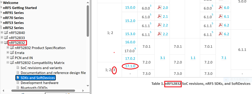
  • It is recommended to use nRF_SDK v17.1.0 or later versions to write code for the third edition


Credit to Nordic Infocenter website:
https://infocenter.nordicsemi.com/topic/comp_matrix_nrf52840/COMP/nrf52840/nRF52840_ic_rev_sdk_sd_comp_matrix.html


Credit to Nordic Infocenter website:
https://infocenter.nordicsemi.com/topic/comp_matrix_nrf52832/COMP/nrf52832/ic_rev_sdk_sd_comp_matrix.html


  • For further clarity on the differences between the second edition IC Bluetooth modules and the third edition IC Bluetooth modules, the following table and links are provided for reference


Edited by Sales Manager: Ms. Mandy Chao

Raytac Corporation 勁達國際電子股份有限公司
Bluetooth & WiFi module maker based on Nordic nRF54, nRF53, nRF52, nRF7002 solution
BT5.4 &BT5.3 & BT5.2 & BT5.1 Qualified, FCC/IC/CE/Telec/KC/RCM/SRRC/NCC Pre-Certified. Bluetooth Solution: nRF54, nRF5340, nRF52840, nRF52833, nRF52832, nRF52820, nRF52811, nRF52810, nRF52805, nRF51822 WiFi Solution: nRF7002
www.raytac.com
email:service@raytac.com
Tel: +886.2.3234.0208