
To help you quickly get started with Raytac’s AN7002 Wi-Fi module and nRF5340 module, here’s a simple guide on how to set up the development and programming environment using AN7002Q-nRF5340 Demo Board(AN7002Q-DB-5340)and nRF5340 DK.
This article will cover the 4 sections below:
1. Hardware setup
2. Software Development Kit and Environment setup
3. Programming/Development
4. Flashing/Uploading firmware
1. Hardware Setup
1 x Nordic nRF5340-DK: PCA10095(2.0.0)
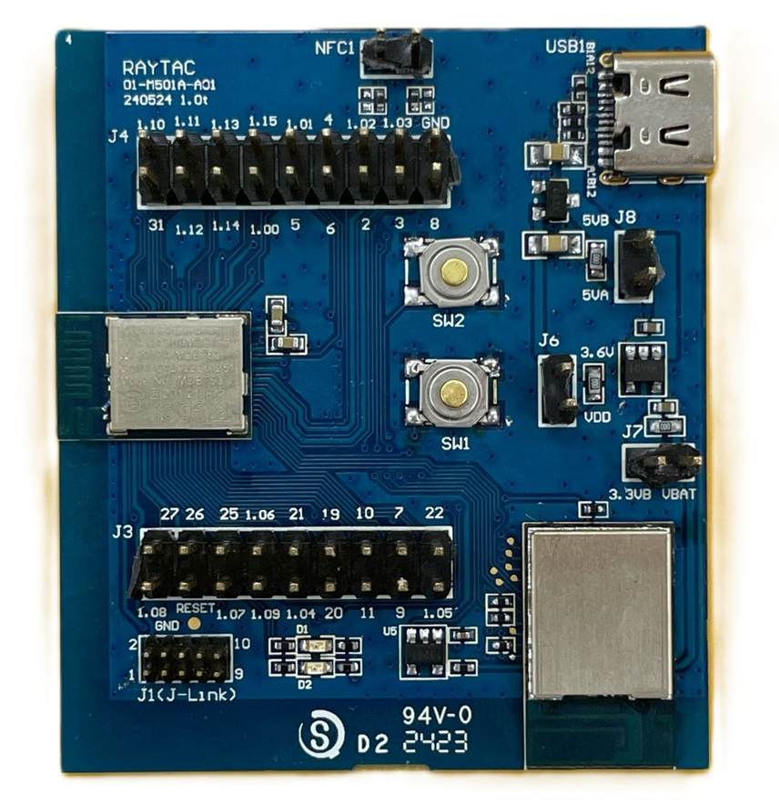
1 x Raytac AN7002Q-DB-5340
1 x IDC Cable
1 x USB-Micro USB Cable
1 x USB-Type C USB Cable
*Note: You need to use both the “Nordic nRF5340-DK” and “Raytac AN7002Q-DB-5340 demo board” together for programming and development. *
Steps to connect the hardware:
- Connect J-Link on Nordic DK to AN7002Q-DB-5340 using IDC Cable
- Power Nordic nRF5340-DK up using Micro USB Cable
- Power Raytac AN7002Q-DB-5340 up using Type C USB Cable

AN7002Q-DB-5340 Schematic Diagram:

2. Software Development Kit and Environment Setup
Download nRF Connect For Desktop: Download nRF Connect For Desktop (Please Click Me)
Download nRF Command Line Tools: Download nRF Command Line Tools (Please Click Me)
(1) Download and install the latest version of nRF Connect for Desktop
(Windows 64-bit – 5.0.0 version)
nrfconnect-setup-5.0.0-x64.exe

(2) Download and install the latest version of nRF Command Line Tools
(Windows X86 64 – 10.24.2 version)
nrf-command-line-tools-10.24.2-x64.exe
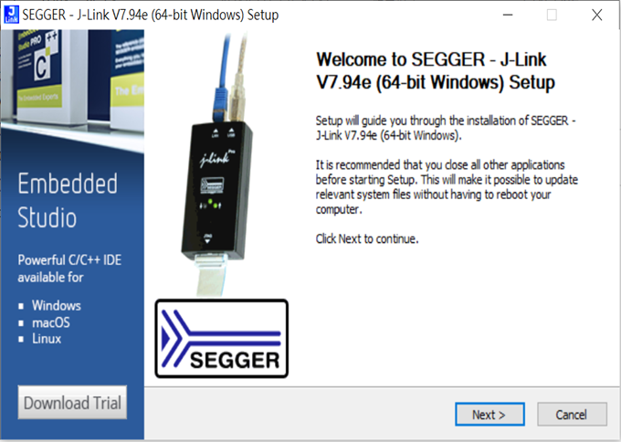
*Note: During set-up, the SEGGER J-LINK installation/update request might pop up on your screen. *
*(As shown in below screenshot). *
If you’re initiating Segger J-Link Driver, please check the guideline here(Click me)
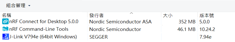
After the installations are completed, you can see the following applications under the:
“Programs and Features” section in the Control Panel.
nRF Connect SDK (NCS) supports development using the free VS (Visual Studio) Code IDE.
Here’s how to select and install the NCS SDK version (nRF Connect SDK vx.x.x):
Step1.
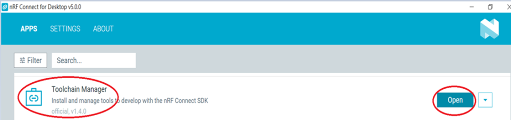
Open “nRF Connect for Desktop” → Choose “Toolchain Manager” → then click” Open”
Step2.
You’ll see a list of nRF Connect SDK versions. It’s recommended to install NCS v2.6.0 or later.
Here, we use NCS v2.6.0 as an example.
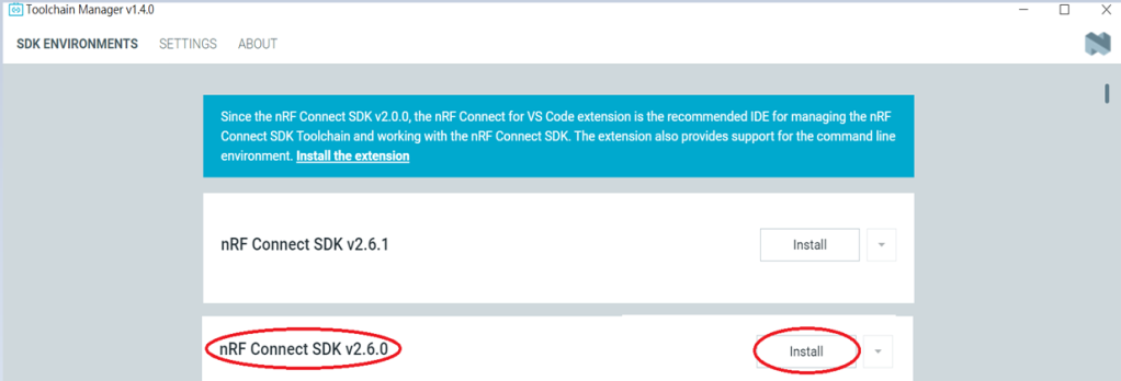
Step3.
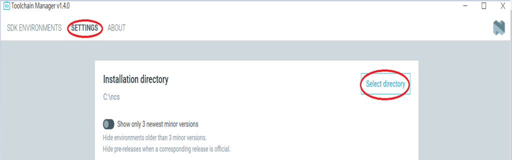
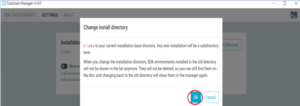
Before installing NCS v2.6.0, confirm the installation path (Default path → C:\ncs).
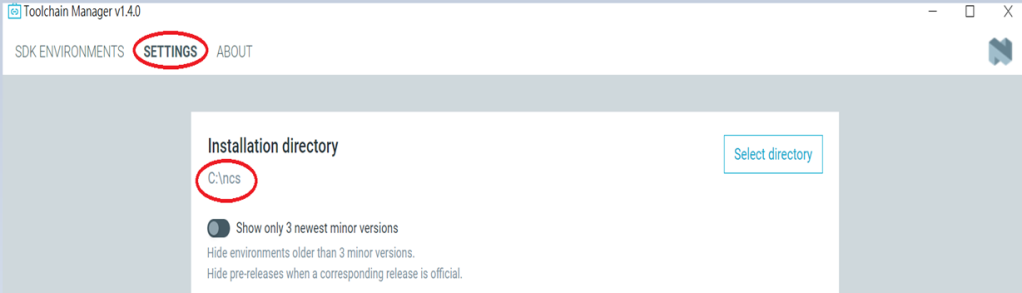
If you want to change the path, click “Select directory”, and press OK.
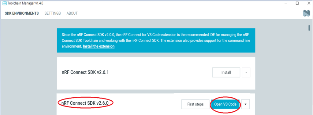
Step4.
After installing the nRFConnect SDK v2.6.0, click “Open VS Code”.
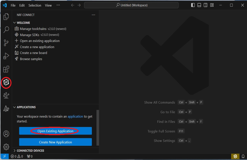
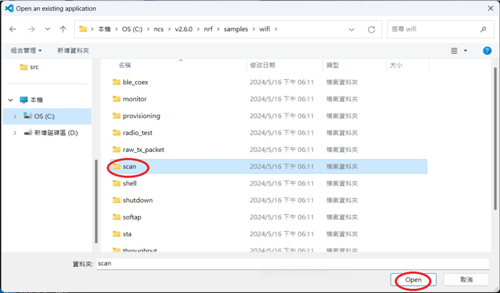
Step5.
Open the Wi-Fi scan example
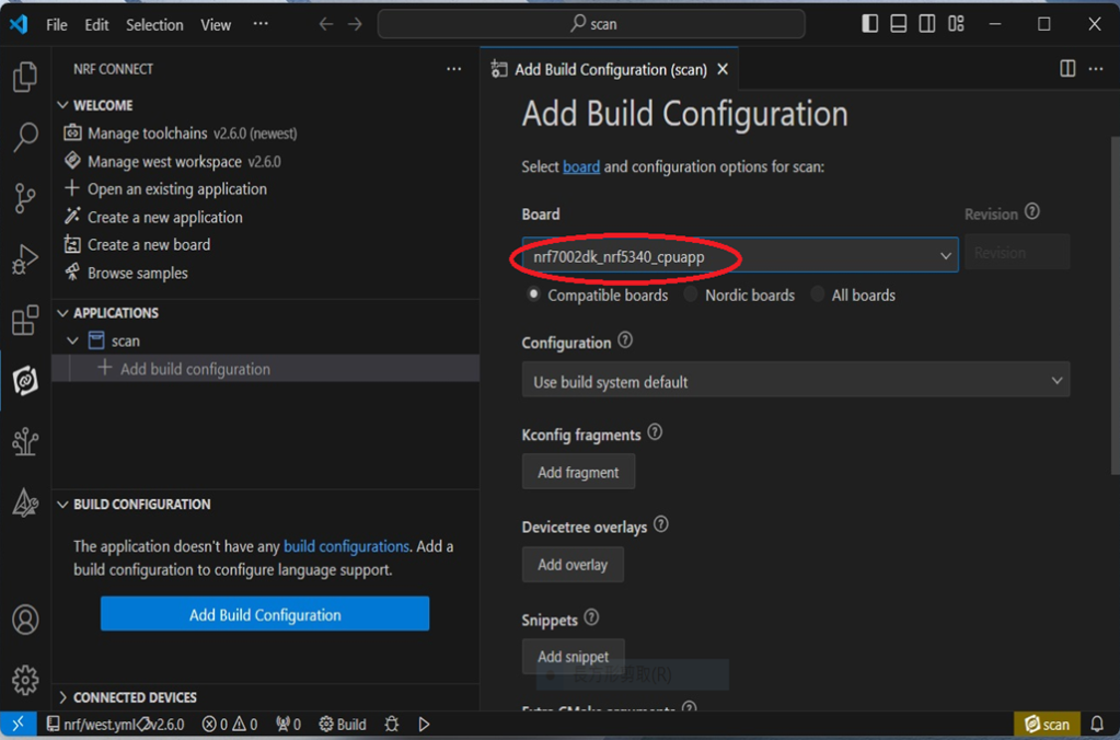
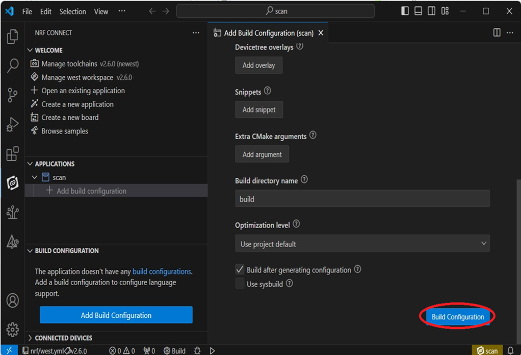
Step6.
Add build configuration → select the board and compile.
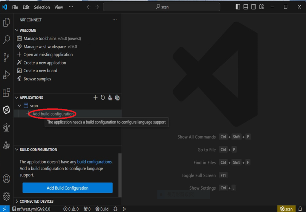
Select board: nrf7002dk_nrf5340_cpuapp.
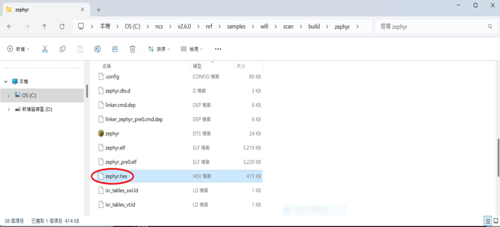
Step7.
After compilation, a hex file will be generated.
Step8.
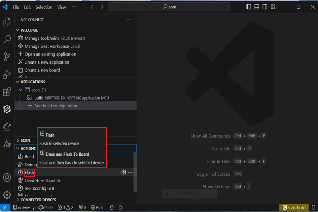
Under ACTIONS, you can choose to Build, Debug, or Flash.
Build:
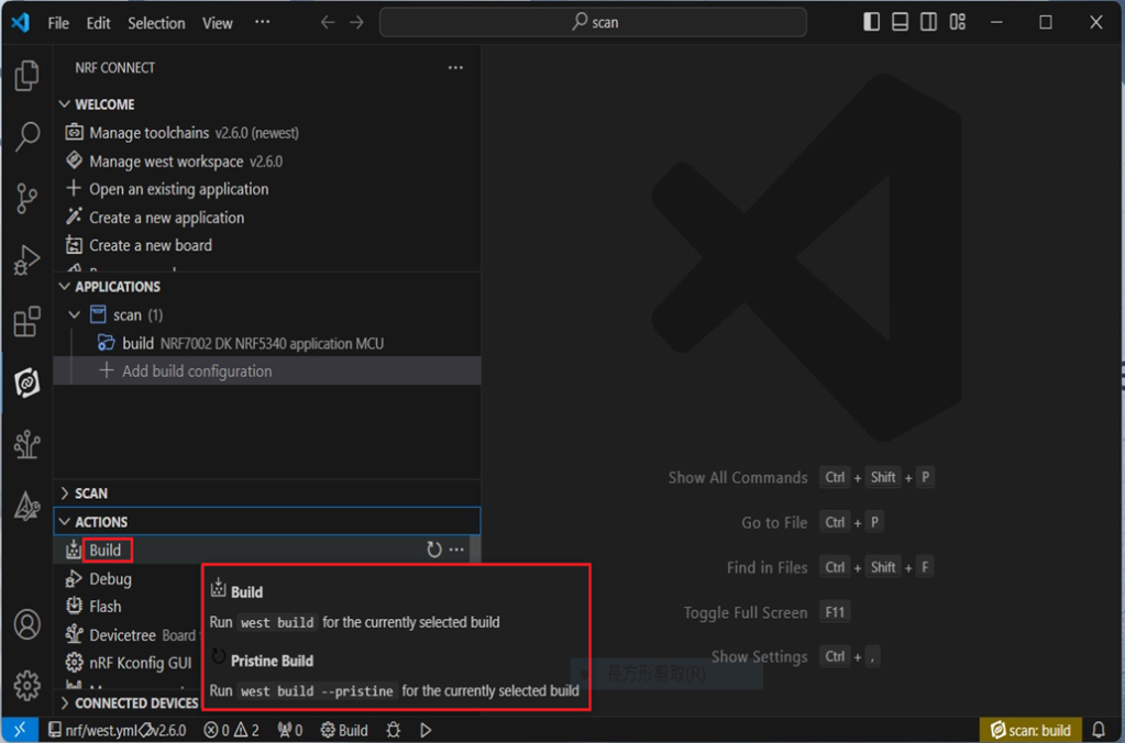
Debug:
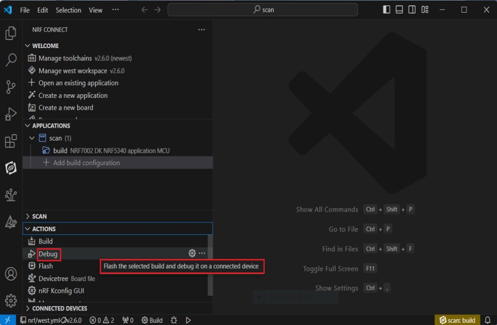
Flash:
4. Programming
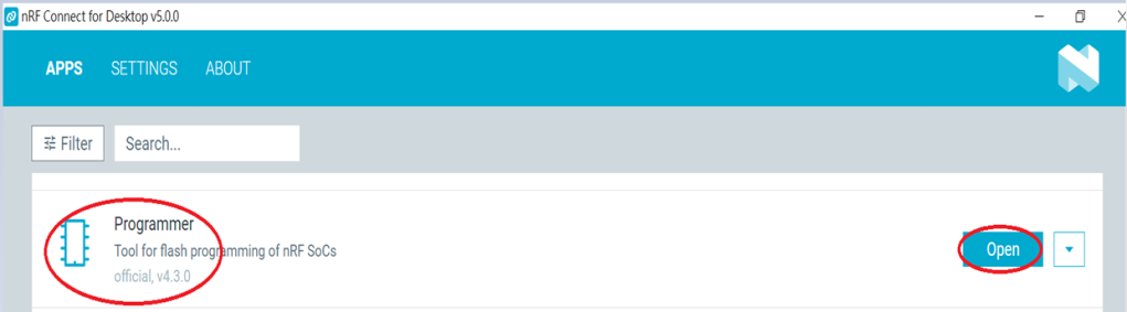
nRF Connect SDK(NCS) supports programming. You can use the “Programmer” tool to flash .hex file.
Here’s how:
Step1.
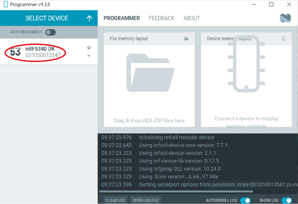
Open “nRF Connect for Desktop” → Select “Programmer” → then click” Open”.
Click “Select Device”;
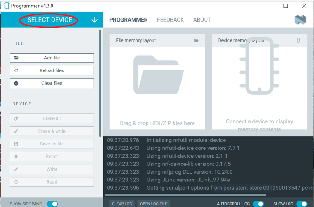
Since AN7002 Wi-Fi IC does not act as an MCU,
we can only flash the .hex file into the MDBT53(nRF5340) BLE IC.
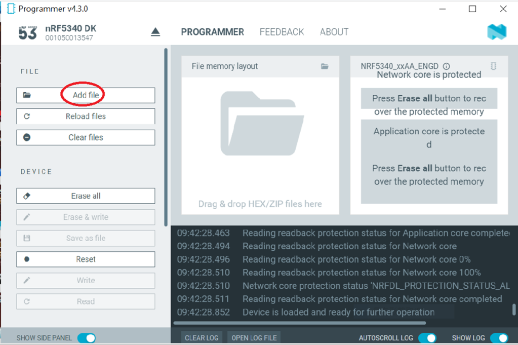
Click “Add file” to add the .hex file.
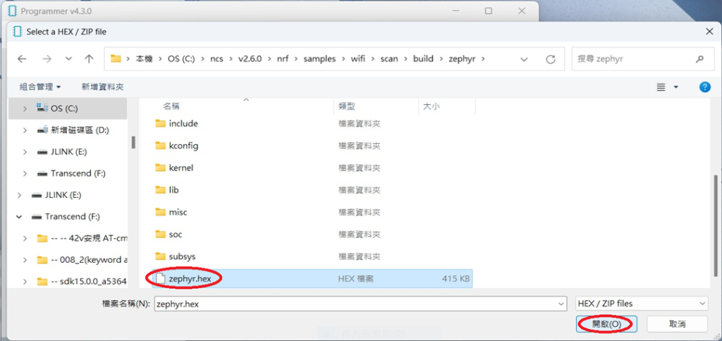
Step2.
Select the .hex file you want to flash.
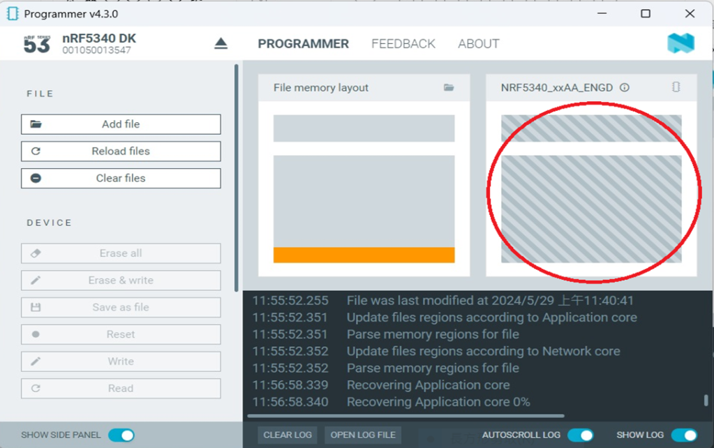
The hex file will be written into the part of the memory layout (where orange part is highlighted).
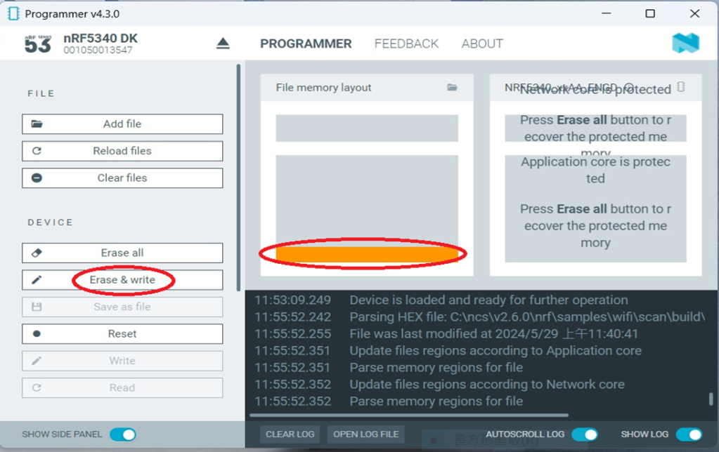
Slashes will be displayed in the circled part during the flash process.
Step3.
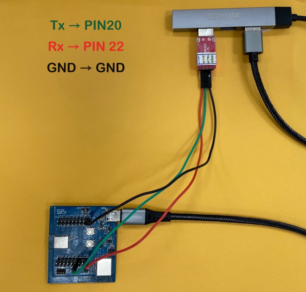
Once the flash process is completed, connect Raytac’s AN7002Q-DB-5340 development board to PuTTY.
Tx to p0.20
Rx to p0.22
GND to GND
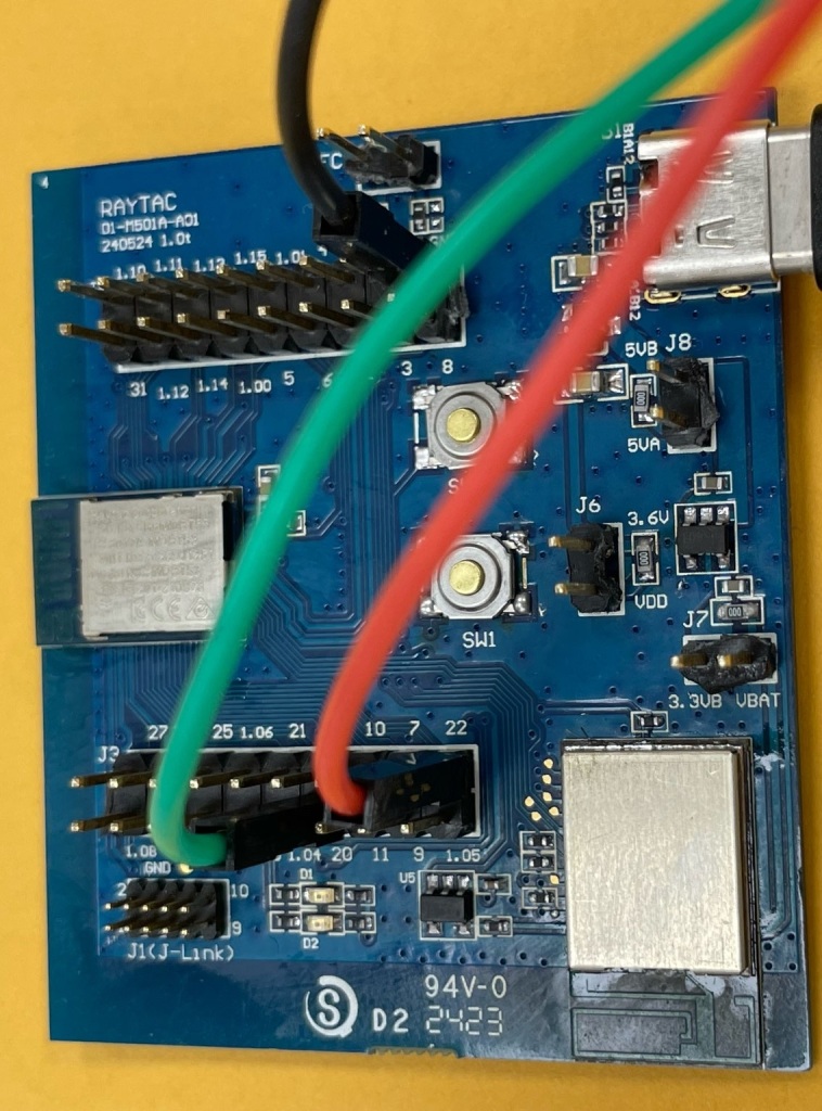
This is a closer look into the pins that will be connected.
The flash process is completed when the LOG is displayed as circled below.
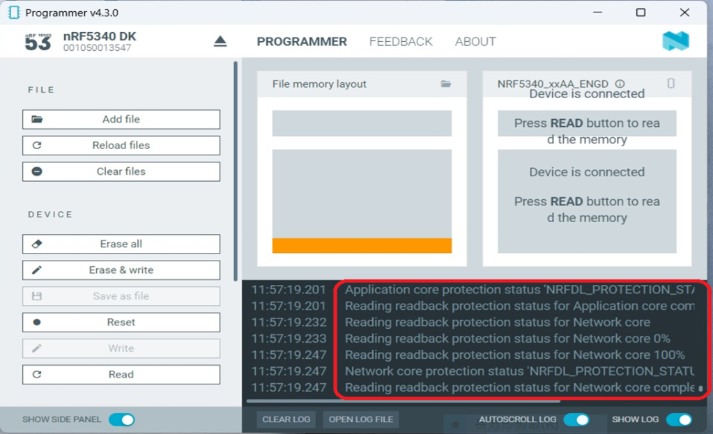
Check if hardware connection is successful using PuTTY.
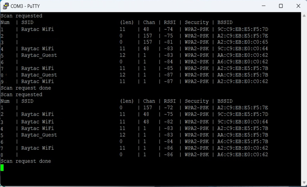
*2024-Aug-12 update:*
Before running Scan code / Station code / Shell code:
You must ensure that the MAC address has already been programmed into the module.
Click on this link to learn more about how to load the MAC address.
Useful references:
Edited by Sales Manager: Ms. Vicky Huang
Technical guidance provided by R&D Manager: Mr. MW Lee
Hardware environment provided by Hardware Engineer: Mr. Kyle Wang
Raytac Corporation 勁達國際電子股份有限公司
Bluetooth & WiFi module maker based on Nordic nRF54, nRF53, nRF52, nRF7002 solution
BT5.4 &BT5.3 & BT5.2 & BT5.1 Qualified, FCC/IC/CE/Telec/KC/RCM/SRRC/NCC Pre-Certified.
Bluetooth Solution: nRF54, nRF5340, nRF52840, nRF52833, nRF52832, nRF52820, nRF52811, nRF52810, nRF52805, nRF51822
WiFi Solution: nRF7002
http://www.raytac.com
email: service@raytac.com
Tel: +886-2-3234-0208
No comments:
Post a Comment