Wednesday, November 22, 2023

Navigating RF Certification: A Guide to DTM and Radio Testing

 RF Test – DTM & Radio Test

When launching new products, there is a requirement for RF testing, and two methods are commonly used:

DTM (Direct Test Mode) and Radio Test.


Nordic's SDK provides two RF testing programs: DTM (Direct Test Mode) and Radio Test. While both methods can test RF indicators, they have some distinctions. DTM follows the Bluetooth specification's Direct Test Mode data format (referenced in Bluetooth Core Specification Version 5.2, Vol. 6, Part F.), primarily for Bluetooth certification tests.

On the other hand, Radio Test focuses on the chip's radio indicators, making it more suitable for FCC and ETSI certifications.

Let's delve into detailed explanations for DTM and Radio Test programs.


DTM(Direct Test Mode)

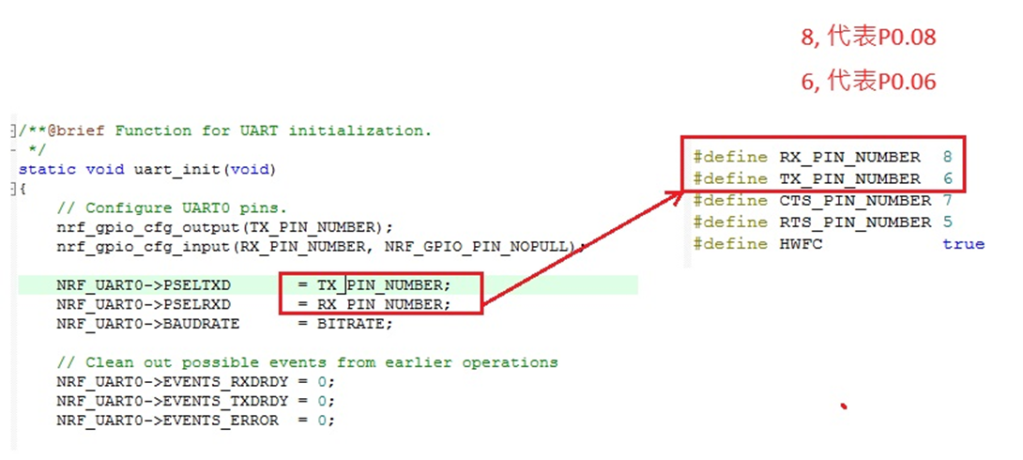
The Bluetooth Association offers a feature for testing RF characteristics. Nordic has incorporated DTM firmware into the SDK according to SIG standard documents. Customers only need to modify the Baud Rate and UART TX/RX pins to conduct RF tests.

1. Download and install nRF Connect for desktop software and nRF5 SDK from the Nordic website.

nRF Connect for desktop download:

https://www.nordicsemi.com/Software-and-tools/Development-Tools/nRF-Connect-for-desktop/Download


nRF5 SDK download:

https://www.nordicsemi.com/Software-and-tools/Software/nRF5-SDK/Download#infotabs


2. Install the Direct Test Mode program in the nRF Connect for desktop software.


3. Extract the SDK package, open the DTM example code from

nRF5_SDK_vxx\examples\dtm\direct_test_mode\ board number\blank, modify TX and RX pins based on the target board's definitions, then compile.

Download the program to the target board connected to the PC.
(Select the appropriate sample code based on the IC/module for testing, referring to the  board number below. )


IC P/Nboard number
NRF52832pca10040
NRF52810pca10040e
NRF52840pca10056
NRF52811pca10056e
NRF52833pca10100
NRF52820pca10100e

RF testing is performed using UART TX/RX commands.
The SDK program defaults to certain positions, but users can modify these two pin positions according to their product design without changing the Baud Rate setting.

UART PinnRF51nRF52
TXDP0.09P0.06
RXDP0.11P0.08


4. Use nRFConnect DTM for testing by adjusting UART TX/RX pins.
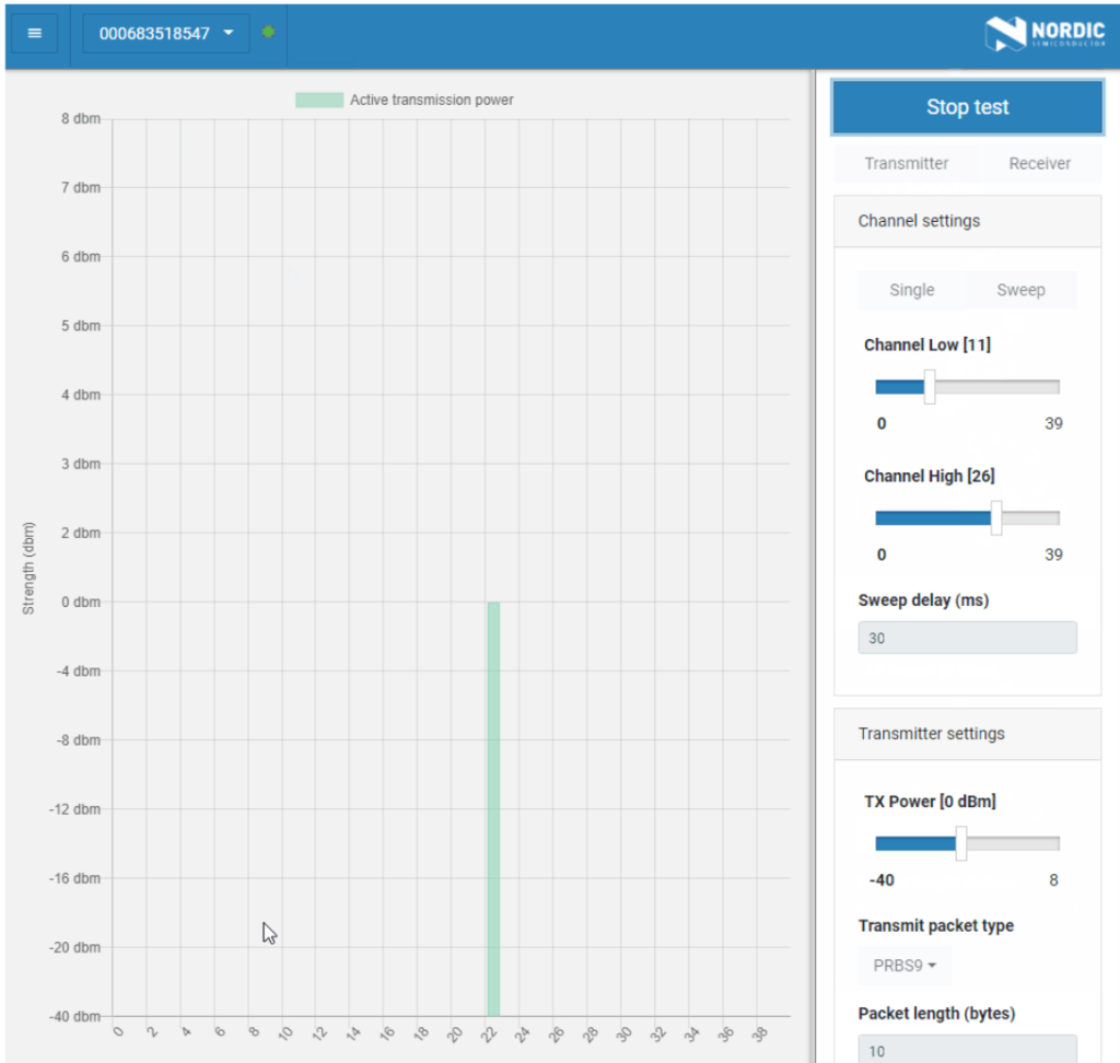
Please refer to Video tutorial from link below:
https://github.com/NordicSemiconductor/pc-nrfconnect-dtm/blob/master/resources/screenshot.gif


Radio Test

Nordic provides a tool for simpler RF testing, allowing the configuration of radio-related data such as TX power, frequency, TX carrier, and TX modulation carrier through a Command List. It doesn't include testing for RX sensitivity; if needed, users must either write a program for this test or use DTM for testing.

1. Open from nRF5_SDK_vxx\examples\peripheral\radio_test\board number\blank
(Based on the IC/module for testing, referring to the board number below.)

IC P/Nboard number
NRF52832pca10040
NRF52810pca10040e
NRF52840pca10056
NRF52811pca10056e
NRF52833pca10100
NRF52820pca10100e


2. This test also utilizes a Command-based approach to send instructions for different parameter tests. Compared to DTM, Radio Test is more flexible, offering a wider range of RF parameters to test.
The connection method between the target board and PC, serial port modifications, and the approach with DTM are identical.


3. Use the command-Line interface (CLI) through the serial port to control and test the output power, bitrate, and channel settings of the radio parameters during testing.

Additionally, configure the CLI to enable the 32 MHz high-frequency crystal oscillator.

The application allows setting scanning mode with intervals ranging from 1 millisecond to 99 milliseconds (per 1 millisecond) for each channel.


4. Refer to the Nordic CLI commands documentation for the command testing method.
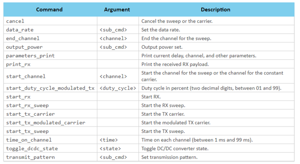
https://infocenter.nordicsemi.com/index.jsp?topic=%2Fcom.nordic.infocenter.sdk5.v15.2.0%2Fnrf_radio_test_example.html&cp=4_0_0_4_5_29_0&anchor=nrf_radio_test_example_commands

5.Testing

Lastly, we can utilize Spectrum to test PCBA RF characteristics.


Edited by Sales Manager: Ms. Vicky Huang
Raytac Corporation 勁達國際電子有限公司
A BT5.2 & BT5.1 & BT5 module maker based on Nordic nRF53 & nRF52 solution
(nRF5340 & nRF52840 & nRF52833 & nRF52832 & nRF52820 & nRF52811 & nRF528

Wednesday, October 25, 2023

Exploring the Influence of Keep Out Zones on Antenna Performance in Layout

 Keep Out Area

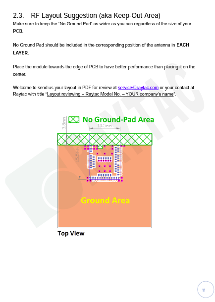
The "keep out area" in a module, particularly when it comes to electronics and antennas, serves several critical purposes:

  1. Electromagnetic Isolation: One of the primary functions of the keep out area is to maintain electromagnetic isolation. It ensures that other components, conductive traces, or structures are not placed too close to the antenna. This is vital to prevent interference and maintain the antenna’s radiation pattern and performance.

  2. Preventing Mutual Interference: Electronic components, especially those generating electromagnetic radiation, can interfere with the antenna’s operation if placed too closely. The keep out area enforces a minimum distance to prevent such interference and maintain the antenna’s signal quality.

  3. Optimizing Radiation pattern: Antennas have specific radiation patterns that dictate how they transmit and received signals. The keep out area helps ensure that the antenna’s radiation pattern remains unobstructed. Placing components within this area can alter the pattern and reduce antenna efficiency.

  4. Safety and Compliance: Compliance with safety and regulatory standards is crucial in electronic devices. The keep out area may be mandated by these standards to minimize the risk of electromagnetic exposure for users and to ensure the device operates within allowable limits.

  5. Thermal Considerations: Some components generate heat during operation. The keep out area can also account for thermal considerations, ensuring that heat-producing components do not adversely affect the antenna's performance due to temperature-induced changes in materials or interference.

  6. Mechanical Clearance: Besides electromagnetic concerns, the keep out area can also provide mechanical clearance, ensuring that the antenna is not physically obstructed by other components or structures.

In summary, the keep out area in a module is a critical design aspect that aims to maintain the integrity, performance, and safety of the antenna system within an electronic device by managing electromagnetic, thermal, mechanical, and regulatory considerations.


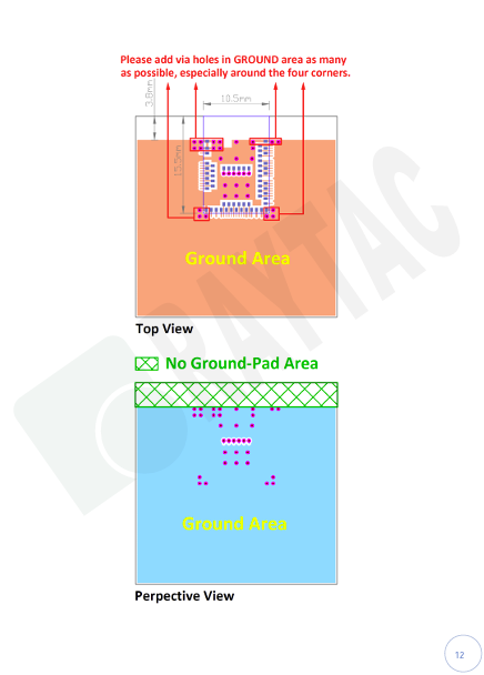
Use following module as our example, you are recommend referring to our specification link on page 12-13 for RF layout suggestions (Keep out area.)

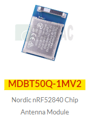
MDBT50Q-1MV2 (<-Click me for Product details)

Specification:                                                                              
[nRF52840] MDBT50Q-1MV2 & MDBT50Q-P1MV2 Spec (Ver.L) (<-Click me for Specification details)

Design Guide includes:
MDBT50Q & MDBT50Q-P & MDBT50Q-U Footprint_Design Guide (230606) (<-Click me and find the corresponding doc name for download.)

  • Footprint (compatible for Protel, Eagle, Altium Design)
  • 2D/3D drawing
  • Reflow/Solder Profile
  • Spec for external 32.768KHz

Instruction to find out selected module’s specific/design guide etc:

Following below steps after link to Raytac Corporation official webpage, click on yellow highlighted texts to find and download selected module’s specific/design guide etc … accordingly.

1.  Raytac Corporation official website

2.

3.


Edited by Sales Manager: Ms. Mandy Chao
Raytac Corporation 勁達國際電子有限公司
A BT5.2 & BT5.1 & BT5 module maker based on Nordic nRF53 & nRF52 solution
(nRF5340 & nRF52840 & nRF52833 & nRF52832 & nRF52820 & nRF52811 & nRF52810 & nRF52805)
http://www.raytac.com email: service@raytac.com Tel: +886.2.3234.0208

Wednesday, September 6, 2023

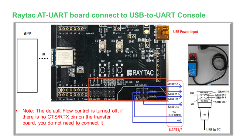
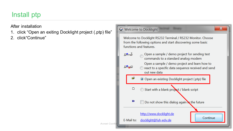
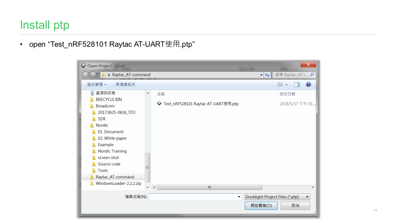
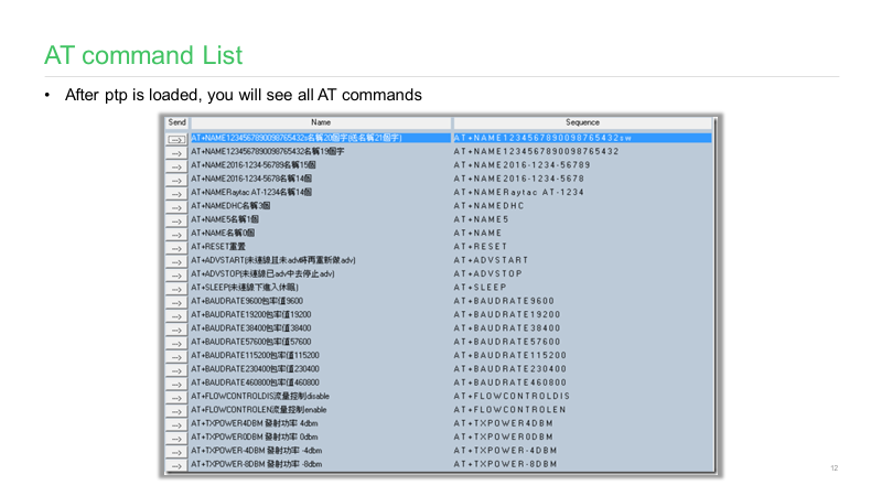
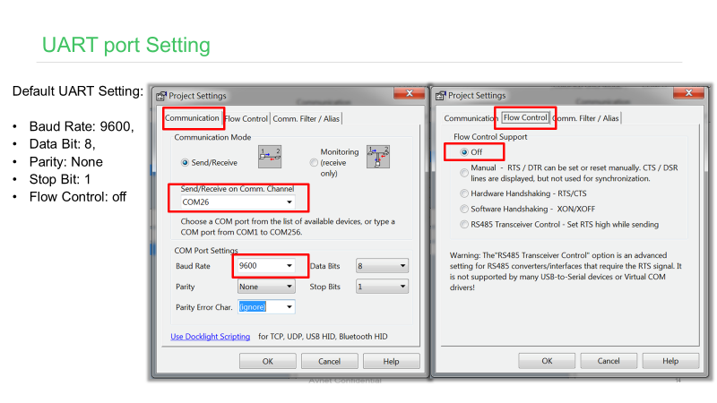
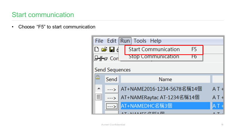
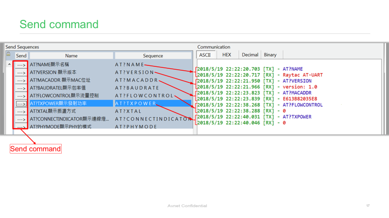
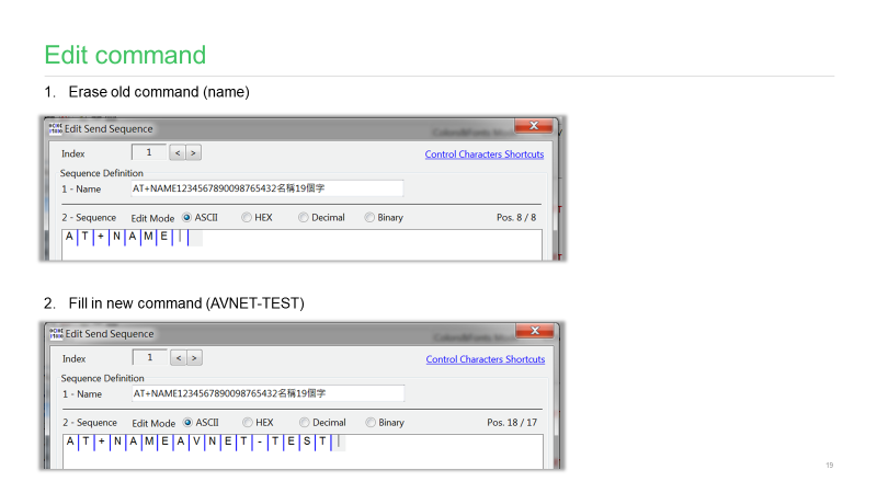
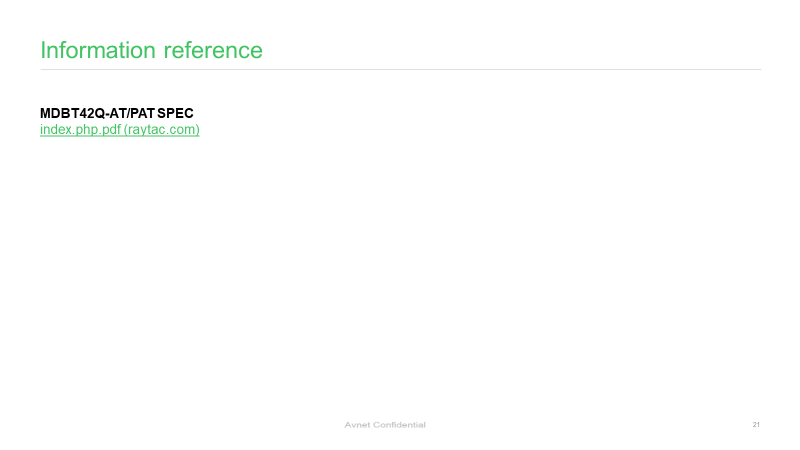
AT Command Tutorial: MDBT42Q-AT/PAT

AT commands play a crucial role in wireless communication, IoT, and embedded systems.

This guide aims to assist developers in creating an appropriate environment for efficient AT command usage, ensuring smooth communication and application operation.

Credit to Hanyu Hsu /Avnet Taiwan.

Edited by Sales Manager: Ms. Mandy Chao
Raytac Corporation 勁達國際電子有限公司
A BT5.2 & BT5.1 & BT5 module maker based on Nordic nRF53 & nRF52 solution
(nRF5340 & nRF52840 & nRF52833 & nRF52832 & nRF52820 & nRF52811 & nRF52810 & nRF52805)
http://www.raytac.com email: service@raytac.com Tel: +886.2.3234.0208

Wednesday, August 30, 2023

SRRC Certification Update - Document No. 129

 About SRRC Certification:


SRRC, or the State Radio Regulation Committee, is a mandatory certification required by the National Radio Management Committee of the Ministry of Industry and Information Technology of China. All wireless products sold within China must obtain certification, commonly referred to as SRRC certification, which involves approval of the wireless transmission equipment model.

SRRC Document No. 129:

Document No. 129 introduces various interference avoidance technical requirements for wireless transmission equipment, including "pre-transmission scanning," "monitoring and avoidance," and "Medium Utilization (MU)" for equivalent occupancy rate.

a. "Pre-transmission scanning" and "monitoring and avoidance" mechanisms involve monitoring and listening to the wireless channel before or during signal transmission. By setting appropriate detection threshold levels, the channel's occupancy status is determined to select an idle channel for access.

b. The "equivalent occupancy rate" mechanism requires wireless transmission equipment to self-adjust based on parameters such as "Duty Cycle" and "transmission power," ensuring the "equivalent occupancy rate" remains at a lower level (not exceeding 10%).


1.     Certificate Validity Period:
Enforced from October 15, 2023. During this period, both old and new policies can be applied. Certificates obtained under the old regulation (Document No. 353) are valid until December 31, 2025. However, certificates obtained by complying with the requirements of Document No. 129 will be valid for 5 years.


2.     Sample Requirements:
2.1   The quantity of conducted samples prepared according to the old regulation remains unchanged: 5 samples.
2.2   The major change introduced by Document No. 129 is the addition of interference avoidance technical requirements. The interference avoidance test items include:
1.     Maximum channel occupancy time
2.     Minimum channel idle time
3.     Minimum silence period duration
4.     Detection of unused signals
5.     Detection threshold
6.     Short control signal duty cycle
7.     Equivalent occupancy rate.


Differences between Old and New Regulations:


Edited by Sales Manager: Ms. Vicky Huang
Raytac Corporation 勁達國際電子有限公司
A BT5.2 & BT5.1 & BT5 module maker based on Nordic nRF53 & nRF52 so

Monday, August 14, 2023

Tips for Nordic’s nRF52840 DK to successfully detect Raytac’s MDBT50Q-DB-40 Demo Board

 WHY Nordic’s DK cannot DETECT Raytac’s modules?

Some tips to fix this problem

Nordic’S board no : PCA10056 (nRF52840)

Raytac’s board no : MDBT50Q-DB-40 (nRF52840)


1. Update the version of nRF Command Line Tools from below link
https://www.nordicsemi.com/Products/Development-tools/nRF-Command-Line-Tools/Download?lang=en#infotabs

2. Update the version of jlink driver from below link.
https://www.segger.com/downloads/jlink/JLink_Windows_V780c_x86_64.exe


3. Update the version of nRF Connect for desktop.
nRF connect for desktop V4.1.2
Programmer V3.0.9


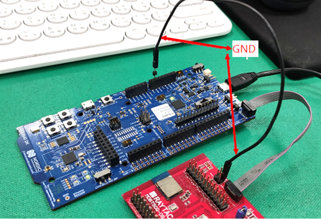
4. Add jumper wire for GND shown as the below red arrow to avoid the different power reference between these 2 boards.


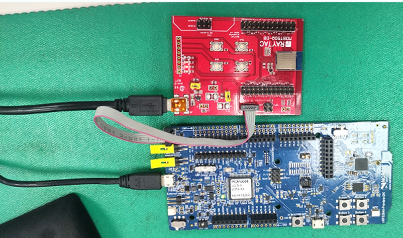
5. Make sure that IDE cable connects correctly. Red edge of IDE cable should connect to PIN 1 of both boards.

6. Supply power to VDD of Raytac’s demo board before flashing.


Edited by Sales Manager: Ms. Gracie Chuang
Raytac Corporation 勁達國際電子有限公司
A BT5.2 & BT5.1 & BT5 module maker based on Nordic nRF53 & nRF52 solution
(nRF5340 & nRF52840 & nRF52833 & nRF52832 & nRF52820 & nRF52811 & nRF52810 & nRF52805)
http://www.raytac.com email: service@raytac.com Tel: +886.2.3234.0208