
Hi there, folks!
Here introduce the hardware setting perspective to burn your firmware onto MDBT50Q-RX Dongle.
(if you are looking for firmware coding setting, please visit "Firmware Coding & DFU onto MDBT50Q-RX")
So you have hopefully downloaded your IDE, you have written your code which you then plan to copy it over onto your MDBT50Q-RX and make it execute your master plan to take over the world!
Seriously, don't underestimate the Nordic nRF52840 based MDBT50Q-RX. USB sticks with Bluetooth can do wonders ;)
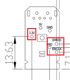
So, first of all, in order to be able to burn your code onto the USB Dongle, you will have to know the nerdy parts which includes which pins you will have to connect to. In our very well documented specification sheet for MDBT50Q-RX on section 8 which is called "Reference Circuit", you will find parts down to the left that has "3.3V/SWDIO/SWCLK/GND" marks on it:

Further down in the specification sheet, in section 9, you will find pictures illustrating where exactly on the PCB you can find these pins:
Now we know what to look for and where they are, so now we have only got to tell you how to use them.
Some people might not know this, but for developing these things, you need to get something called J-Link to connect your MDBT50Q-RX to your desktop. However, since this J-Link, when buying the official one from SEGGER, is very expensive, we strongly recommend you to just buy the nRF52840-DK from Nordic Semiconductor as it can be used as a J-Link through their software development kit (SDK) called nRFgo Studio and is MUCH CHEAPER than the official J-Link from SEGGER is.
Sidenote: There are a couple of other reasons why you should just get your hands on a nRF52840-DK from Nordic Semiconductor instead of getting a SEGGER J-Link, but that's not the topic of this post ;)
When this is done, this is finally how you connect your MDBT50Q-RX to your J-Link to make it all work:
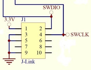
Here you will have to pay attention to the fact that you have to connect J-Link pins 3, 5 & 9 to GND. Otherwise, you won't be able to burn anything onto your dear MDBT50Q-RX.
The physical connection should look like this:
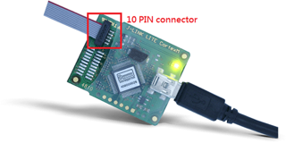
Pay attention to the direction of the cable, because that will also matter. The direction we mean in this case is which way the slim strip of red is facing.
As we have just revised our MDBT50Q-RX, our customers who have been developing firmware for our USB dongle should take a look at our previous blog post in which we explain about the changes made or contact us directly at service@raytac.com
Have a good day and we at Raytac wish you smooth and happy tinkering :)
Here introduce the hardware setting perspective to burn your firmware onto MDBT50Q-RX Dongle.
(if you are looking for firmware coding setting, please visit "Firmware Coding & DFU onto MDBT50Q-RX")
So you have hopefully downloaded your IDE, you have written your code which you then plan to copy it over onto your MDBT50Q-RX and make it execute your master plan to take over the world!
Seriously, don't underestimate the Nordic nRF52840 based MDBT50Q-RX. USB sticks with Bluetooth can do wonders ;)
So, first of all, in order to be able to burn your code onto the USB Dongle, you will have to know the nerdy parts which includes which pins you will have to connect to. In our very well documented specification sheet for MDBT50Q-RX on section 8 which is called "Reference Circuit", you will find parts down to the left that has "3.3V/SWDIO/SWCLK/GND" marks on it:

Further down in the specification sheet, in section 9, you will find pictures illustrating where exactly on the PCB you can find these pins:
Now we know what to look for and where they are, so now we have only got to tell you how to use them.
Some people might not know this, but for developing these things, you need to get something called J-Link to connect your MDBT50Q-RX to your desktop. However, since this J-Link, when buying the official one from SEGGER, is very expensive, we strongly recommend you to just buy the nRF52840-DK from Nordic Semiconductor as it can be used as a J-Link through their software development kit (SDK) called nRFgo Studio and is MUCH CHEAPER than the official J-Link from SEGGER is.
Sidenote: There are a couple of other reasons why you should just get your hands on a nRF52840-DK from Nordic Semiconductor instead of getting a SEGGER J-Link, but that's not the topic of this post ;)
When this is done, this is finally how you connect your MDBT50Q-RX to your J-Link to make it all work:
Here you will have to pay attention to the fact that you have to connect J-Link pins 3, 5 & 9 to GND. Otherwise, you won't be able to burn anything onto your dear MDBT50Q-RX.
The physical connection should look like this:
Pay attention to the direction of the cable, because that will also matter. The direction we mean in this case is which way the slim strip of red is facing.
As we have just revised our MDBT50Q-RX, our customers who have been developing firmware for our USB dongle should take a look at our previous blog post in which we explain about the changes made or contact us directly at service@raytac.com
Have a good day and we at Raytac wish you smooth and happy tinkering :)
Raytac Corporation 勁達國際電子有限公司
A BT5 & BT 4.2 & BTv4.1 module maker based on Nordic nRF51 & nRF52 solution
(nRF51822 & nRF51422 & nRF52832 & nRF52810 & nRF52840)
A BT5 & BT 4.2 & BTv4.1 module maker based on Nordic nRF51 & nRF52 solution
(nRF51822 & nRF51422 & nRF52832 & nRF52810 & nRF52840)
| www.raytac.com | email: cs@raytac.com | Tel: +886.2.3234.0208 |
No comments:
Post a Comment